Understanding how valve end connections impact your system’s total cost of ownership (TCO) and long-term operational safety.
Why Valve End Connections Dictate Your System’s Lifespan
In the world of fluid handling, a valve is only as reliable as its interface with the piping system. While engineers often focus on the internal mechanisms—such as the plug, disc, or seat—the valve connection is where the most critical failures occur. According to industrial maintenance data, over 60% of unplanned piping shutdowns are caused by leakages at connection points rather than internal valve failures.
Selecting the right valve connection types is a balancing act between absolute leak prevention (permanence) and the need for maintenance accessibility (removability). Choosing the wrong standard, such as using an NPT thread in a high-vibration system or mismatched flange ratings, leads to catastrophic mechanical stress and fatigue. For procurement and plant managers, this decision directly impacts the Total Cost of Ownership (TCO). A single hairline leak in a critical high-pressure line can easily incur $10,000 to $50,000 per hour in unplanned downtime, moving the needle from a simple CAPEX purchase to a vital OPEX strategy.
Maintenance Frequency + Pressure Rating + Media Toxicity = Your Optimal Connection Choice.
Threaded End Connections: Low Cost, High Risk?
Threaded or scored connections are the most common solution for small-diameter piping (usually under 2 inches). They are valued for their low initial cost and the fact that they can be installed without specialized welding equipment. However, they carry inherent risks in industrial environments.
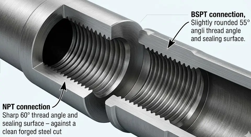
The Mechanical Difference Between NPT and BSPT
The two most dominant standards for threaded connections are NPT (National Pipe Thread) and BSPT (British Standard Pipe Taper). Mixing these up is a common “rookie error” that leads to immediate leaks.
| Standard | Thread Angle | Taper Angle | Sealing Mechanism |
|---|---|---|---|
| NPT (ASME B1.20.1) | 60° | 1° 47′ | Metal-to-metal wedge with sealant |
| BSPT (ISO 7-1) | 55° | 1° 47′ | Metal-to-metal wedge with sealant |
Tapered threads create a seal by the physical deformation of the threads as they are tightened, effectively “wedging” the connection shut. This requires the use of PTFE tape or pipe dope to fill the microscopic gaps at the root of the threads.
The Vibration Trap and Wall Thickness Rule
While convenient, threaded connections are prone to “fatigue failure.” Under cyclic thermal stress or high vibration (such as near a reciprocating pump), the root of the thread acts as a stress concentrator. Over time, micro-cracks can lead to the valve snapping off at the connection point.
Additionally, standard engineering practice dictates that threaded steel pipe should have a minimum wall thickness of Schedule 80 to compensate for the metal removed during threading when used in critical process lines. Schedule 40 is generally only acceptable for low-pressure utility lines (like basic water or air).
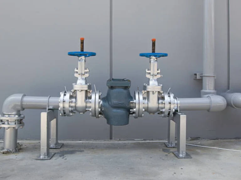
Flanged End Connections: The Industry Standard for Maintenance
For systems requiring regular cleaning, inspection, or replacement, flanged connections are the “King of Maintenance.” Whether you are installing a robust 4 flanged gate valve or a high-performance butterfly valve, flanges provide a bolted interface that can be easily disassembled without destroying the pipe.
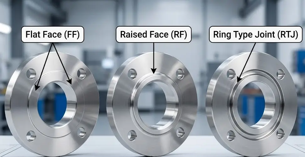
Deciphering RF, FF, and RTJ Face Types
The success of a flange connection depends on the “Face” type. Mismatching these can lead to broken valve bodies, especially in cast iron units.
- Flat Face (FF): Used mostly in low-pressure applications. The entire surface is flat, requiring a full-face gasket. Never bolt an RF steel flange to an FF cast iron valve, as the uneven torque will crack the cast iron flange.
- Raised Face (RF): The most common industrial type. The gasket surface is raised slightly above the bolting circle, concentrating more pressure on a smaller gasket area for a better seal.
- Ring Type Joint (RTJ): The choice for extreme pressure (Class 600 and above). It uses a metal ring that sits in a machined groove, creating a metal-to-metal seal under high bolt tension.
Flange Ratings and the Reality of Bolt Torque
A common misconception is that a Class 150 flange can handle 150 PSI regardless of temperature. According to ASME B16.5, the pressure-temperature rating is dynamic. For instance, a carbon steel (Material Group 1.1) Class 150 flange rated for 285 PSI at ambient temperature drops to exactly 200 PSI at 400°F, and further down to 170 PSI at 500°F. Ensuring proper bolt torque is critical; uneven loading is the #1 cause of gasket blowout in flanged systems.
Welded End Connections: The Zero-Leakage Guarantee
When the media is toxic, high-pressure steam, or hazardous chemicals, “zero leakage” is the only acceptable standard. Welded connections turn the valve and pipe into a single, continuous metal unit.
Socket Weld (SW): Fast but Flawed for Corrosive Media
In a Socket Weld, the pipe is inserted into a recessed area of the valve and fillet welded around the edge. It’s fast and requires no complex alignment. However, there is a catch: the expansion gap. Standard engineering practice requires a 1.6mm (1/16 inch) gap at the bottom of the socket to allow for thermal expansion. This gap creates a “stagnant zone” where corrosive fluids can pool, making Socket Welds unsuitable for highly corrosive applications.
Butt Weld (BW): The Ultimate High-Pressure Solution
For large pipes, extreme pressures, and corrosive fluids, Butt Weld is the gold standard. The ends of the valve and pipe are beveled (usually a V-bevel) and joined with a full-penetration weld. This creates a smooth flow path with no crevices, reducing turbulence and erosion. The only downside is that it is permanent; maintenance requires physically cutting the valve out of the line.
Compression Connections: The Instrument Specialists
Not every valve connection involves massive main pipes. Small-bore systems, such as those using a solenoid valve connection for analytical instrumentation or a control valve connection for precision impulse lines, rely heavily on compression fittings.
These systems utilize a professional Double Ferrule mechanism—pioneered by industry standards like Swagelok or Parker. When the nut is tightened, the front ferrule creates a primary pressure seal against the valve body, while the back ferrule hinges inward to tightly grip the tubing. This “bite” creates a high-pressure, vibration-resistant seal without the need for heat, welding, or threading the tube itself. In heavy industrial processes, these metallic double ferrule joints are the exclusive choice to ensure zero leakage under rigorous instrument calibration cycles.
The Hidden Killer: How Actuator Torque and Vibration Destroy Weak Connections
Many engineers make the mistake of selecting a valve connection based solely on static pressure standards. However, in automated fluid control, the real danger is Dynamic Torque. When a powerful electric or pneumatic actuator cycles a valve rapidly, the mechanical force creates a leverage effect on the connection points.
VINCER Engineering Insight: At Vincer, we evaluate the entire mechanical system before recommending a solution. Relying on over 10 years of fluid control experience and a dedicated team of 10+ engineers, we apply an “8-Dimension Analysis” (evaluating media, temperature, pressure, connection standard, control method, material, industry characteristics, and installation space). For high-torque automation systems, we calculate the cantilevered weight of the actuator to advise whether you need to upgrade flange ratings or customize reinforced mounting brackets, ultimately preventing fatigue failure at the interface.
The Ultimate Engineer’s Decision Tree: Matching Connection to Application
To simplify your selection process, follow this logical decision tree to find the safest and most cost-effective connection type for your piping system.
Step 1: What is the pipe size?
Proceed to Step 2A: Assess the Media.
- Is it an Instrument/Impulse Line (< 1/2″)?
→ Choose: Compression (Double Ferrule) - Is the fluid highly toxic or under extreme pressure (but NOT highly corrosive)?
→ Choose: Socket Weld (SW) - Is the fluid highly corrosive?
→ Choose: Butt Weld (BW) or Flanged - Is it low-pressure water, air, or non-hazardous?
→ Choose: Threaded (NPT/BSPT) *Sch 80+ recommended for process lines; Sch 40 acceptable for utility lines.
Proceed to Step 2B: Assess Maintenance Frequency.
- Does the valve require regular removal, cleaning, or inspection?
→ Choose: Flanged (RF/RTJ) - Is it a permanent installation with lethal media or high-pressure steam?
→ Choose: Butt Weld (BW)
Navigating Standards (ASME/API) and the Reality of Custom Dimensions
While ASME B16.10 provides standard “face-to-face” dimensions, engineers often find themselves in a tight spot where a standard valve simply won’t fit into a pre-existing, cramped piping envelope, or a legacy machine requires a non-standard thread depth.
The Vincer Advantage in Manufacturing: When standard valves cannot meet your space limitations, customized dimensions become essential. Vincer operates an ISO9001-certified 7,200m² factory equipped with 12 CNC machines and 30 conventional lathes, allowing us to control the entire production process. For urgent custom orders that require altering face-to-face dimensions, our coordinated team utilizes machining from forged blocks and our standard is 7-10 working days which ensures you get the exact fit for your piping envelope.