Understanding the Lithium Battery Manufacturing Landscape
Walk into a modern gigafactory and the scale hits you immediately: one finished cell rolls off the line every second, with nearly 90% of the operation automated from slurry mixing to final quality testing. The global lithium-ion battery chain is on track to grow at roughly 30% each year through 2030, pushing the market past $400 billion as electric vehicles, grid storage, and consumer electronics drive unprecedented demand.
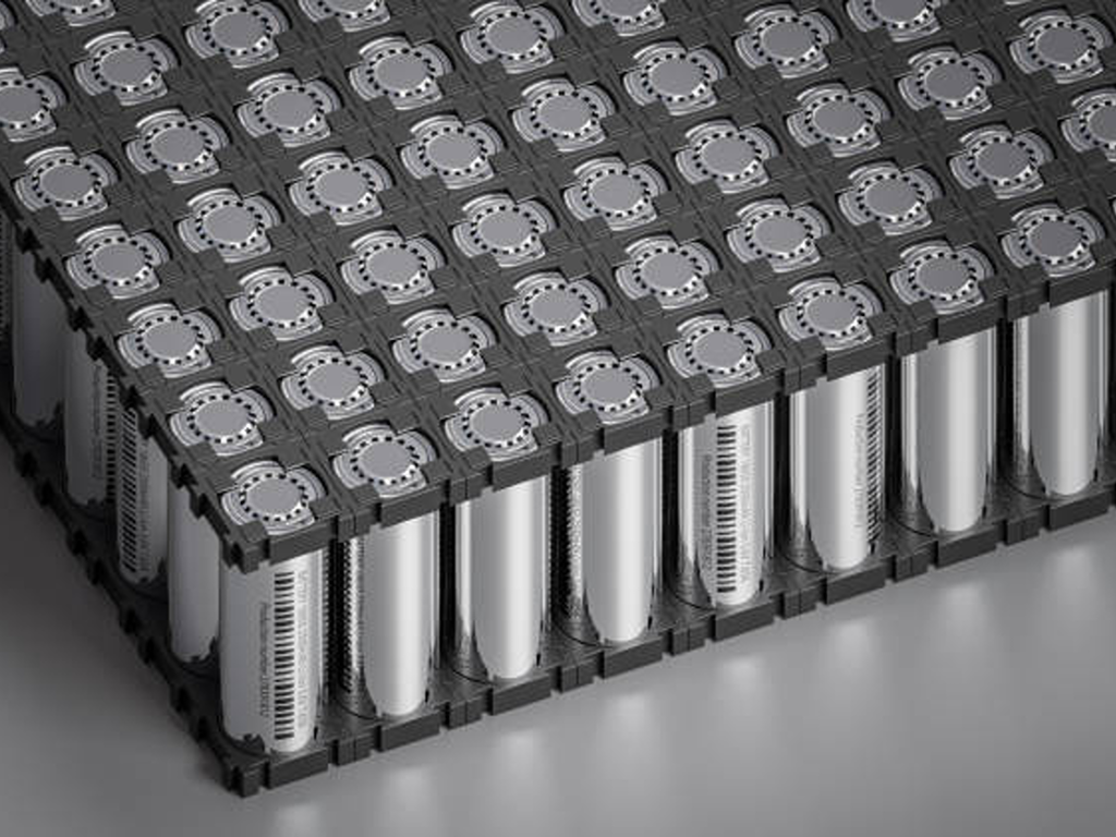
Behind these numbers sits a manufacturing process that is less “assembly” and more precision chemical engineering. Making a lithium-ion battery means controlling material compositions at the micron level, keeping dew points below ≤ -50°C in critical zones, and managing thousands of fluid transfer points — all while hitting production rates measured in cells per second.
The full manufacturing chain breaks into four stages: electrode manufacturing, cell assembly, cell finishing (formation and aging), and the often-overlooked infrastructure layer of fluid handling and industrial valves that runs through all of them. Electrode fabrication accounts for roughly 40% of total manufacturing cost, cell assembly about 20%, and formation — the most time-consuming single step — consumes around 32% (Fraunhofer FFB, 2025). Equipment selection alone can swing cell costs by 15–30%, which means getting the process right isn’t just an engineering concern. It’s a commercial one.
This guide walks through each stage, covering the equipment, precision parameters, and fluid handling components that separate a production line that makes excellent batteries from one that makes merely adequate ones.
Electrode Manufacturing — Where Battery Performance Is Determined
Every battery engineer learns one truth early: you cannot fix a bad electrode downstream. The electrochemical foundation laid at this stage — active material ratios, coating uniformity, compaction density — governs energy density, cycle life, and safety for the cell’s entire service life. The electrode is the battery’s heart. Everything after is packaging and validation.
Slurry Mixing — The Formula That Sets Everything in Motion
Before a single micron of electrode is coated, the raw materials must become a homogeneous slurry. The cathode side typically combines NMC (nickel-manganese-cobalt) or LFP (lithium iron phosphate) active material with conductive carbon black, PVDF binder, and NMP (N-methyl-2-pyrrolidone) solvent. The anode side uses graphite or silicon-graphite composite with CMC/SBR binders in a water-based system.
Getting the mix right means controlling two critical parameters: solid content (typically 50–70%) and viscosity (2,000–10,000 cP for cathode, 1,000–5,000 cP for anode). Traditional batch mixing relies on planetary mixers — think industrial-scale stand mixers — where each batch runs independently. The newer approach, continuous twin-screw extrusion, feeds materials through a co-rotating screw system that mixes and conveys simultaneously. The difference is stark: continuous extrusion cuts energy consumption by up to 95% compared to batch processes (Eirich MixSolver data) while delivering 3–5× the throughput with better batch-to-batch consistency.
For production planners, the choice between batch and continuous mixing comes down to product mix. Running a single formulation at high volume? Continuous extrusion wins almost every time. Switching chemistries frequently — NMC one day, LFP the next? Batch mixing offers faster changeover, despite the efficiency penalty.
Coating and Drying — The Precision Deposition Stage
Once the slurry is ready, it’s applied to metal foil current collectors — aluminum for the cathode, copper for the anode — using slot-die coating, the industry standard for high-volume production. The slurry flows through a precisely machined die head positioned within microns of the moving foil, laying down a wet film of exact thickness.
The precision requirements leave no room for error. China’s Ministry of Industry and Information Technology (MIIT) mandates coating thickness control within ±2 μm and areal density deviation under ±1% for regulated battery manufacturers. At a production line running 30–80 meters per minute, holding that tolerance demands closed-loop feedback that adjusts die position and pump speed in real time.
Drying follows immediately, and the energy meter starts climbing fast. The coated foil passes through a multi-zone convection oven — or increasingly, a hybrid laser-assisted system — to evaporate the solvent. Between them, drying and the dry room environment consume over 75% of total manufacturing energy (IDEEL Project, Fraunhofer ILT, 2024). Solvent recovery is mandatory on both economic and environmental grounds: closed-loop NMP recovery systems from suppliers like Dürr Group reclaim over 90% of the solvent.
A major emerging alternative is dry electrode processing. Fraunhofer IWS’s DRYtraec technology — which won the Joseph von Fraunhofer Prize in 2025 — feeds a dry powder mixture through a calender gap where shear forces fibrillate the binder, mechanically interlocking the particles into a continuous electrode film. No solvents, no drying ovens, no NMP recovery. The process cuts energy consumption by roughly 25% and capital costs by about 30%, and it’s already licensed to a major European automaker for mass production.
Calendering and Slitting — Compacting and Shaping the Electrode
After drying, the coated foil passes through a roll press — the calender — which compresses the electrode to its target porosity, typically 30–40% for NMC cathodes. This step involves a genuine trade-off: higher compaction increases energy density (more active material per unit volume), but excessive compression crushes the pore structure that lithium ions travel through, accelerating capacity fade.
The calender sets the electrode’s final thickness and density profile. Then slitting machines — using laser or mechanical cutting — trim the electrode to precise dimensions. One parameter matters far more than it sounds: burr control. Edge burrs larger than 1 μm can penetrate the separator during assembly or cycling, creating an internal short circuit. MIIT’s 2024 industry guidelines explicitly require burr control at or below this threshold, with electrode alignment accuracy within 0.1 mm.
With the electrodes fabricated, cut, and inspected, they move to assembly — where the form factor question takes center stage.
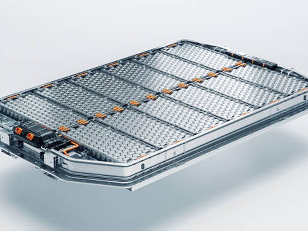
Cell Assembly — Stacking, Winding, and the Automation Imperative
Electrodes are components. A cell is a product. The assembly stage transforms flat electrode sheets and rolls of separator film into the three dominant form factors — cylindrical, prismatic, and pouch — through two competing technical approaches, each with passionate industry advocates.
Stacking vs. Winding — Choosing the Right Assembly Path
Winding is the older, faster technology: the anode, separator, and cathode are layered and wound into a “jelly roll,” much like rolling a scroll. It’s the standard for cylindrical cells (18650, 21700, 4680) and some prismatic designs, running at speeds up to 3,000 mm/s with mature process control and high yield.
Stacking — specifically Z-type stacking — lays individual electrode sheets and separator layers one on top of another, like building a deck of cards. It’s slower (0.1–0.4 seconds per sheet) but achieves measurably better space utilization: a stacked prismatic or pouch cell packs 5–10% more active material into the same volume compared to a wound design, with lower internal resistance and better thermal distribution. This is why BYD’s Blade Battery — a prismatic LFP cell now powering millions of EVs — uses a stacking process.
The industry is tilting toward stacking for high-energy-density applications, especially in EVs. But winding isn’t going anywhere. For cylindrical cells, it remains the only practical assembly method, and the speed advantage is real. Your choice depends entirely on your target cell format and performance requirements.
| Dimension | Winding | Stacking |
|---|---|---|
| Speed | Up to 3,000 mm/s | 0.1–0.4 s/sheet |
| Best for | Cylindrical cells | Prismatic, pouch cells |
| Space utilization | Baseline | +5–10% |
| Internal resistance | Higher | Lower |
| Alignment precision | ±0.5 mm | ±0.2 mm |
| Process maturity | Very high | Improving rapidly |
Electrolyte Filling and Packaging — Sealing in Performance
Once the electrode-separator assembly sits inside its casing — aluminum or steel can for cylindrical/prismatic, aluminum-laminated film for pouch — the cell enters the electrolyte filling station. This step demands extraordinary environmental control.
The electrolyte — typically LiPF6 dissolved in a mixture of carbonate solvents with functional additives — is the medium that shuttles lithium ions between electrodes. It’s also exquisitely sensitive to moisture: trace water reacts with LiPF6 to form hydrofluoric acid (HF), which corrodes the cathode and generates gas. That’s why electrolyte filling happens in an environment with a dew point at or below ≤ -30°C — drier than the Atacama Desert — with precision metering valves hitting fill accuracy within ±0.5%.
After filling, the cell is sealed — laser welding for metal cans (weld width 0.3–0.8 mm, penetration ≥ 1.5 mm) or heat-sealing for pouch cells — and leak-tested, typically with helium, to a leak rate below 1 × 10⁻⁶ Pa·m³/s. Any breach, and the cell’s electrochemical integrity is compromised before it ever sees a charge.
- Targeting cylindrical cells (18650, 21700, 4680)
- Speed is the priority (3,000 mm/s throughput)
- Process maturity and high yield matter most
- Prismatic or pouch cell form factors
- Energy density is the differentiator (+5–10% space)
- Lower internal resistance for better thermal performance
Cell Finishing — Formation, Aging, and Quality Gates
If any step tests a manufacturer’s patience, it’s formation. This is where the assembled cell receives its first charge, and it’s the most time-consuming and expensive single stage in the entire process — roughly 32% of manufacturing cost, taking 1.5 to 3 weeks from start to finish.
Why so long? During that first charge, the electrolyte decomposes in a controlled way at the anode surface, forming a passivation layer called the solid-electrolyte interphase (SEI). This nanometer-thin film is where the electrochemistry gets elegant: it lets lithium ions pass through while blocking further electrolyte decomposition. Get the formation conditions right — current rate, temperature, voltage profile — and you get a uniform, stable SEI that supports over 2,000 charge-discharge cycles. Get them wrong, and you lose 5–10% of the cell’s available lithium to a thick, uneven SEI that keeps growing with every cycle.
After formation, cells enter aging — typically 7–14 days at elevated temperature (around 45°C) or room temperature — where self-discharge behavior gets monitored. Cells whose voltage drops more than roughly 0.5 mV per day get flagged for micro-shorts or contamination and are scrapped. Finally, end-of-line testing sorts cells into quality grades by capacity, internal resistance, and self-discharge rate. For EV applications, only A-grade cells — capacity deviation under 1% and internal resistance spread under 1 mΩ — make the cut.
Industrial Valves and Fluid Handling — The Overlooked Critical Path in Battery Production
Here’s a number that catches most production planners off guard: a single gigafactory deploys several thousand control valves across its fluid handling processes, from slurry preparation and coating line solvent delivery to electrolyte filling and cooling water distribution (Rockwell Automation, GF Piping Systems). Every one of those valves is a potential failure point. The right specification, material choice, and actuation method can mean the difference between consistent product quality and a batch of contaminated cells headed for the scrap bin.
Valve Types by Manufacturing Stage — A Process-by-Process Guide
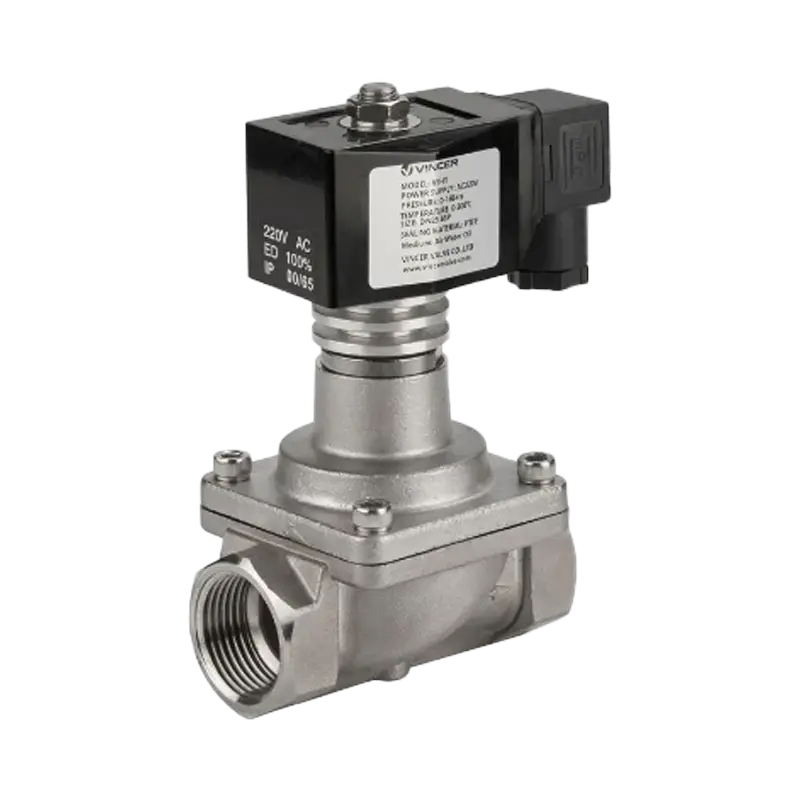
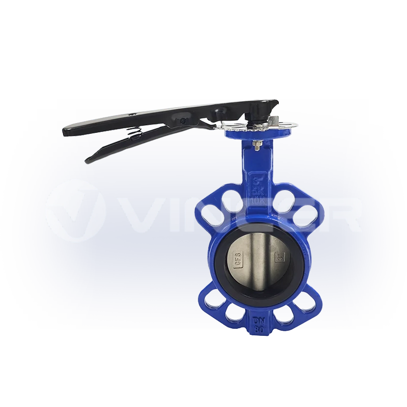
At the slurry mixing station, ball valves and butterfly valves control the precise metering of active materials, conductive additives, binders, and solvents into the mixing vessel. Stainless steel construction (304 or 316L) is standard. The key requirement: minimal dead-leg design to prevent material accumulation that would throw off the next batch’s formulation.
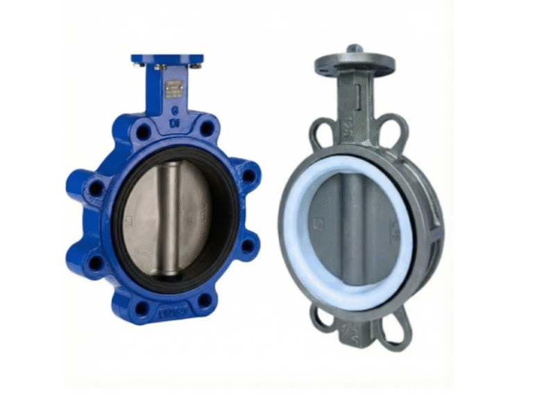
In the coating and drying section, butterfly valves and ball valves on vacuum lines evacuate moist air from the drying chamber, while proportional control valves regulate heated air flow for precise temperature profiles. The challenge at this stage is thermal cycling: valves must hold seal integrity across a wide temperature range while exposed to solvent-laden air streams that degrade standard elastomeric seals.
Electrolyte filling demands the highest-purity fluid handling in the entire plant. High-purity diaphragm valves and pinch valves — with PTFE or PVDF wetted surfaces — meter electrolyte with fill accuracy within ±0.5% in a glovebox environment drier than any natural desert. Metal ion contamination here, even at parts-per-million levels, triggers electrochemical side reactions that degrade cell performance.
The formation and aging area needs vacuum control systems to capture and recover electrolyte vapors and off-gases, while dust collection systems throughout the plant use pulse valves to periodically clear electrode cutting debris from filtration units.
The bottom line: you cannot plan a battery production line without planning its fluid handling infrastructure. And yet, most procurement checklists skip over valve specifications entirely — until the first contamination event forces the issue.
Material Compatibility and Cleanroom Requirements for Battery-Grade Valves
The most expensive mistake a production planner can make with fluid handling isn’t ordering the wrong valve size. It’s ordering valves made of the wrong materials.
Standard industrial valves often contain brass, bronze, or zinc-plated steel components. In a battery production environment, these are contamination time bombs. Copper, zinc, and nickel at concentrations above trace levels act as electrochemical poisons — a few parts per million of dissolved copper in the electrolyte can nucleate dendrites that pierce the separator and cause internal short circuits. This is why battery-grade fluid handling specifications demand copper-free and zinc-free construction, with all wetted surfaces in 316L stainless steel or fluoropolymer-lined (PTFE, PFA, PVDF).
Seal materials are equally critical. The NMP solvent used in cathode slurry and the LiPF6 electrolyte are chemically aggressive. NMP swells and degrades standard NBR (nitrile) seals. LiPF6 in the presence of trace moisture produces HF, which attacks EPDM. The proven alternatives: FKM (Viton) for moderate chemical resistance up to 200°C, and FFKM (perfluoroelastomer) for full chemical compatibility across the entire temperature range — at a significant cost premium.
For the actuation side, pneumatic and electric actuators operating in dry rooms (dew point ≤ -50°C) and cleanrooms (ISO Class 5–7) must be particle-emission-free: sealed designs, no exposed lubricants, no shedding components.
For procurement teams evaluating equipment suppliers, the practical takeaway is straightforward. Look for manufacturers who offer a complete range of automated valve types — ball, butterfly, gate, globe, and control valves — across multiple material grades including 316L stainless steel and PTFE/PFA-lined options, backed by international certifications (ISO 9001, CE, SIL). Suppliers like Vincer, whose automated valve solutions span electric and pneumatic actuation across a full product portfolio with multi-material customization, show the kind of single-source capability that simplifies procurement for multi-stage production lines. When a single contamination event can scrap an entire batch of cells, the cost of properly qualifying your valve supplier is negligible compared to the cost of not doing it.
Key Manufacturing Standards and Compliance Checklist
Every battery that crosses a border must clear a regulatory gauntlet. For production planners and procurement teams, knowing which standards apply — and in what order to pursue certification — avoids costly rework and delayed market entry.
| Standard | Scope | Key Requirement |
|---|---|---|
| UN 38.3 | International transport | 8 tests (T1–T8): altitude, thermal, vibration, shock, short circuit, impact, overcharge, forced discharge |
| IEC 62133-2 | Global product safety (portable) | Electrical, mechanical, and environmental safety for rechargeable cells and packs |
| UL 1642 | United States — cell level | Electrical abuse, mechanical stress, environmental exposure |
| GB 38031-2025 | China — EV traction batteries | Thermal runaway: zero fire, zero explosion for 120 minutes (mandatory July 2026) |
| GB 31241-2022 | China — portable electronics | CCC compulsory certification, effective August 2024 |
| ISO 9001:2015 | Global — quality management | Baseline quality system requirement for most procurement contracts |
The recommended certification sequence: UN 38.3 first — it’s the non-negotiable gatekeeper for international shipping. Then pursue IEC 62133-2 or UL 1642 (cell-level safety) depending on your primary market, followed by any market-specific mandatory certifications (CCC for China, GB 38031 for Chinese EV applications). Using an IECEE CB Scheme member laboratory lets a single set of test data support certification across multiple countries, cutting duplication and cost substantially.
For manufacturing facility compliance, China’s MIIT industry standardization guidelines — revised in 2024 — set quantitative production quality benchmarks: electrode coating thickness control within ±2 μm, burr control ≤ 1 μm, electrolyte filling dew point ≤ -30°C, and mandatory full-lifecycle traceability coding. Any plant supplying the Chinese market must meet these thresholds, no matter where the equipment was made.
Building a lithium battery production line is, at its core, a precision chemical engineering exercise disguised as a discrete manufacturing operation. The companies that get it right — the ones that treat slurry viscosity, dew point control, and valve material compatibility with the same seriousness as cell format and production speed — are the ones whose cells end up powering the EVs and grid storage systems that define the energy transition. The ones that don’t learn the hard way that in battery manufacturing, you cannot inspect quality in at the end of the line. You have to build it in at every step.
References
- Fraunhofer FFB. “Cell Production.” Fraunhofer Research Institution for Battery Cell Production. https://www.batterien.fraunhofer.de/en/competences/cell.html
- Fraunhofer ILT. “IDEEL Project.” 2024. https://www.ilt.fraunhofer.de/
- Fraunhofer IWS. “DRYtraec — Dry Electrode Coating Process.” Joseph von Fraunhofer Prize 2025. https://www.iws.fraunhofer.de/
- Dragonfly Energy. “Inside the World of Battery Cell Manufacturing.” https://dragonflyenergy.com/battery-cell-manufacturing/
- IEEE. “Lithium-Ion Cell Manufacturing Process and Form Factors.” 2024. https://ieeexplore.ieee.org/document/11197089
- Rockwell Automation. “PlantPAx Distributed Control System.” https://literature.rockwellautomation.com/
- GF Piping Systems. “Process Automation for Battery Production.” https://www.gfps.com/
- Festo. “Versatile Automation Components for Battery Manufacturing.” https://festoblog.com/
- Emerson. “Lithium-Ion Battery Component Manufacturing.” https://s1-live.emerson.cn/
- China MIIT. “Lithium-Ion Battery Industry Standardization Conditions (2024 Revision).” http://kfq.jcs.gov.cn/
- The Battery Magazine. “How GB 38031-2025 is Redefining Battery Safety.” https://www.thebatterymagazine.com/
- Element Materials Technology. “Lithium-Ion Battery Certification Guide.” https://www.element.com/
- Vincer Valve. Homepage. https://www.vincervalve.com/
- Vincer Valve. Contact. https://www.vincervalve.com/contact-for-a-quote/