A solenoid valve almost never fails on installation day. It fails three weeks later. A shred of PTFE tape works its way into the pilot orifice. Or the first power cut arrives, and the line you meant to shut keeps flowing. By then the joint is glued, brazed or buried inside a machine frame, and the fix costs far more than the check would have.
The distance between installed and installed right is decided earlier than most people think. Most solenoid valve failures trace back to a handful of decisions, and those decisions belong on the purchase order, not at the valve.
What a Solenoid Valve Does When the Power Is Off
This page covers solenoid valves on fluid process lines: water, air, steam and refrigerant service in sizes from 1/4″ to 4″. Car starter solenoids share the name and are a different animal entirely. Pneumatic directional valves get called solenoid valves too, and much of what follows applies to them, but the piping details here are written for liquid and gas process lines.
The one property that shapes everything else is the de-energized state. A normally closed (NC) valve shuts when power is removed. A normally open (NO) valve opens when power is removed. Picture a blackout at 2 a.m. on a filling line: an NC valve stops the flow, an NO valve keeps the tank filling until it overflows. Neither is more correct. The question is what your system should be doing at that moment with nobody standing there.
Treat that behavior as a specification, not a default. Everything else in a solenoid valve installation either supports that state or quietly works against it. That includes the arrow on the body and the clearance left for a wrench.
Installing the Valve Body: Flow Direction, Sealing and Room to Repair
The half hour spent on the body decides whether the valve comes out again cleanly. The sequence below is short on purpose. Each step carries one judgment that is expensive to get wrong.
Install sequence: six judgments
Depressurize and cool the line
Flush the pipe, install a strainer upstream
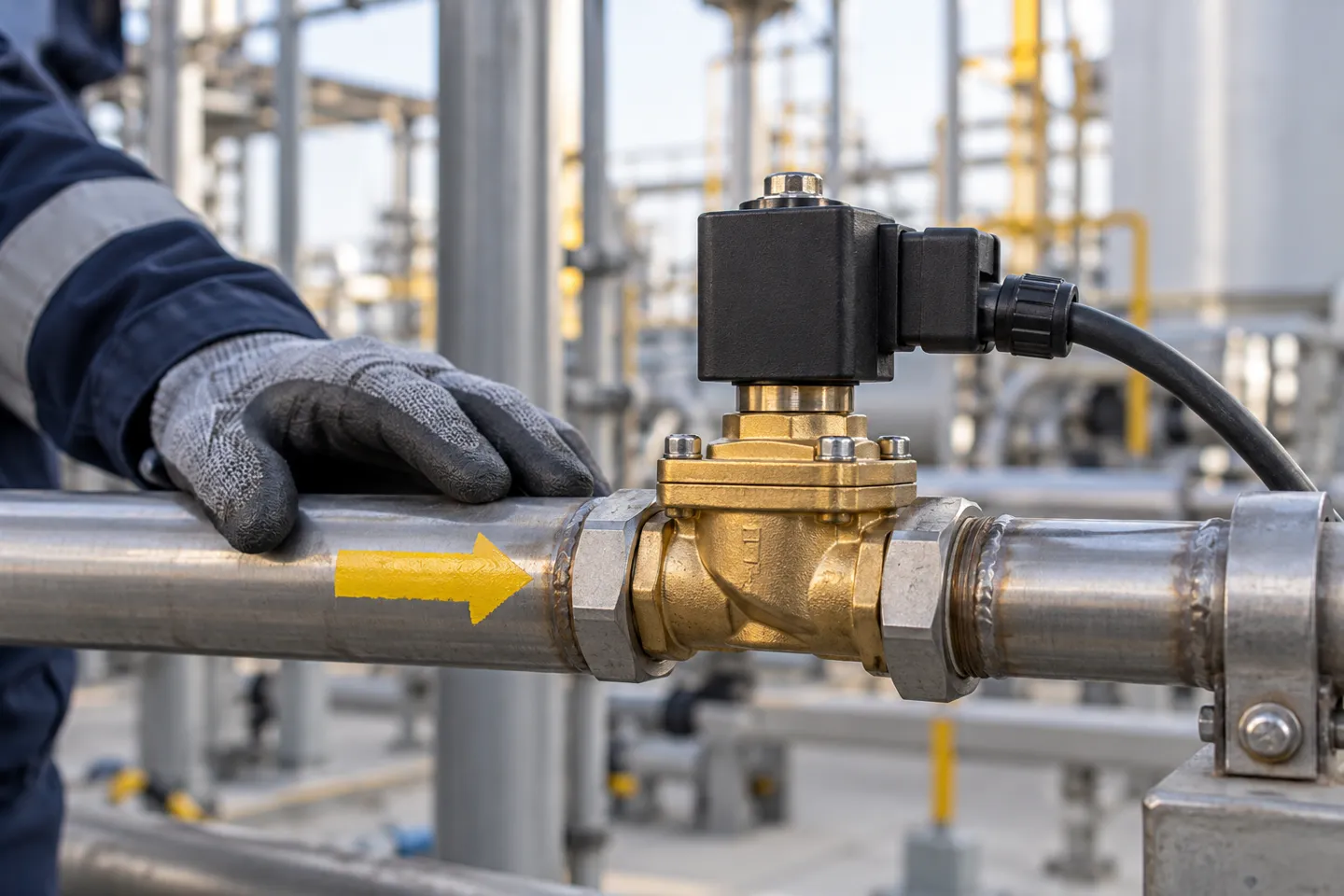
Confirm flow direction against the arrow
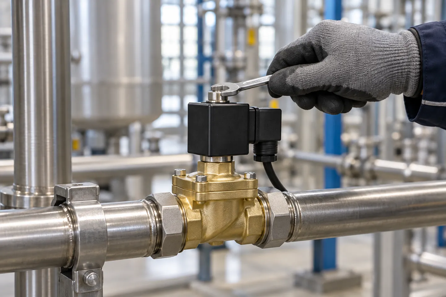
Seal and tighten with a backup wrench
Leave repair space: union or two socket depths
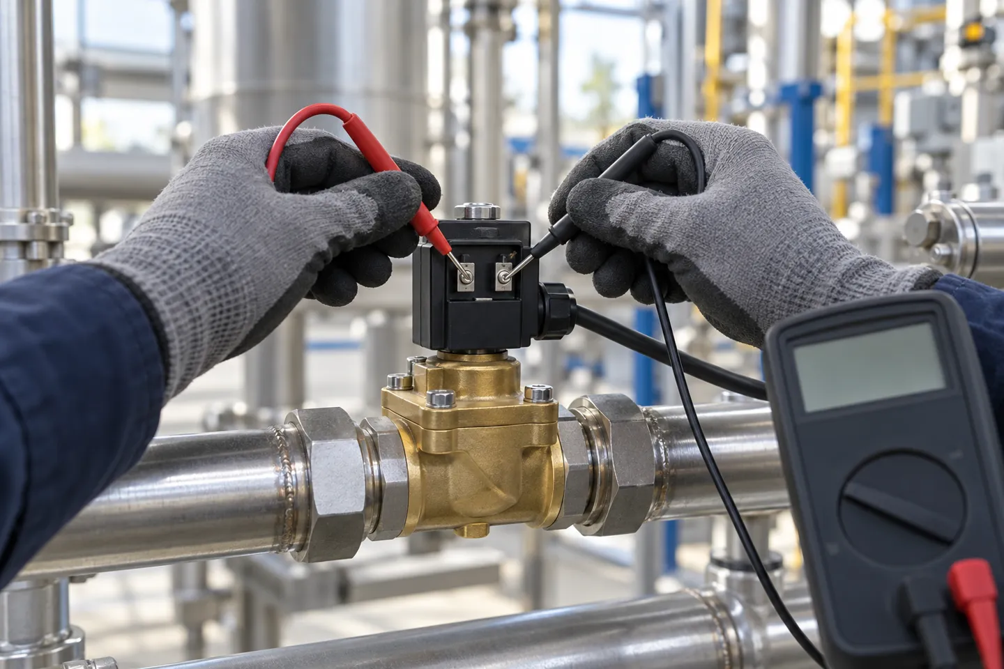
Check coil voltage before first power-up
Check Direction Before You Commit the Joint
Every solenoid valve body carries a flow arrow. Most installers know to look at it. Fewer know what actually breaks when the arrow gets ignored, because a reversed valve usually appears to work.
Pilot-operated and most diaphragm valves use inlet pressure to press the closure disc onto the seat. Plumb the valve backwards and the pressure now works against the seal instead of for it. Water or air still flows through, so the mistake stays invisible during the pressure test. The valve simply never closes again: the actuator clicks, the coil hums, and the line keeps moving. Irrigation techs see this constantly. A reversed valve in a slip-fitted manifold cannot be turned around, so the usual outcome is cutting the whole bank out (r/Irrigation thread, 2025).
| Installed with the arrow | Reversed, day one | Reversed, weeks later | |
|---|---|---|---|
| Flow | Full design flow | Looks normal, flows normally | Still flows |
| Shutoff | Tight closure | Never fully closes | Seat face damaged by backflow and debris |
| Test result | Passes | May pass a crude test | Callback, replacement, cut-out |
Note the middle column. A crude test, open the valve, watch it flow, can pass a reversed valve. The failure shows up the first time the controller asks the valve to shut.
Seal the Thread, Not the Orifice
Two thread standards dominate process piping and they do not interchange. NPT has a 60 degree flank angle, BSP has 55 degrees. Mixing them can start and even seem tight, then weep at the joint for months. Put the thread standard on the purchase order, not just the size.
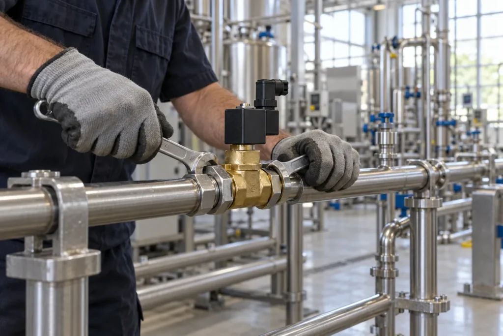
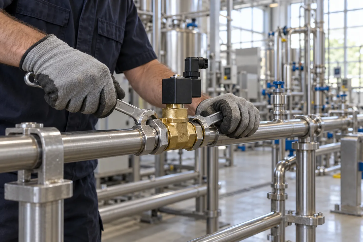
PTFE tape goes on clockwise, two to three wraps. More than that is not extra safety; excess tape shreds off as the joint turns, and those shreds head straight for the small orifices inside the valve, where they cause exactly the stuck-open and stuck-closed behavior that gets blamed on a defective valve. On the wrench side: one hand on the valve body flats, one on the pipe nut. A brass or UPVC body held only by the coil housing twists internally and cracks.
Before any of this, match the coil to the supply. The nameplate voltage and frequency must match the control supply, and a coil should never be energized while it is off the valve, because an unmounted coil has no path to shed its heat and burns out in minutes.
Leave Room to Cut It Out Again
The cheapest insurance in solenoid valve installation is a union, or at minimum two socket depths of clear pipe on one side of every valve. A valve is a service item. Diaphragms tear, coils burn, seats get embedded with debris, and every one of those repairs needs the valve out of the line.
The manifold built with slip fittings butted tight against each other leaves no cut-in point. Replacing one failed valve then means scrapping the bank. The same thread carries dozens of versions of this exact story, and the poster who started the thread above watched three glued valves become landfill over one reversed direction. Whatever the joining method, threaded, glued or flanged, plan the disassembly path while the pieces are still on the bench, not while the line is down.
Mounting Orientation: Why Coil Up Is Not a Universal Rule
Ask whether a solenoid valve can mount sideways and you will collect three confident, contradictory answers. A general-purpose bulletin says orientation is flexible. A refrigeration bulletin says the opposite. Installers’ guides say coil up, always. All three are right, about different valves, and the difference is worth understanding before it costs a coil.
The Armature Tube Decides the Default
Inside the valve sits a plunger that slides in a tube. Grit, scale and mineral particles in the media settle downward. Mount the valve with the coil on top and the armature tube points up, so falling debris lands in the body where the flow flushes it away. Mount it with the tube sideways or down and particles settle into the tube. They pack around the plunger until it sticks. That is the entire mechanism behind the “coil up” recommendation, along with a practical torque note: the coil nut needs to be snug enough that the coil cannot vibrate, around 5 Nm on most pilot valves (Tameson, 2025).
Three Tolerance Classes, Three Rulebooks
| Valve class | Allowed orientation | The catch |
|---|---|---|
| General-purpose water/air, direct-acting small sizes | Horizontal line, on its side, or vertical line | Clean media assumed; dirty media still argues for coil up |
| Refrigerant solenoid valves | MUST be horizontal line, coil housing no more than 45 degrees from vertical (Parker Sporlan, n.d.) | Oil carryover and internal design; deviating risks poor seating and premature coil failure |
| Pilot-operated valves on dirty media | Coil up strongly recommended | Pilot orifice is the smallest gap in the system and clogs first |
The pattern: mounting tolerance is set by internal design and media cleanliness, not by any industry-wide rule. The bulletin that ships with your valve outranks every general guide, including this one. When a supplier cannot state an orientation tolerance for the valve you are buying, that silence is itself information.
Steam, Refrigerant and Washdown Change the Math
Three media push the rules further. Steam service valves use extended stems or bolted yokes to hold the coil away from the hot body, and they belong stem-up so the column shields the coil. Refrigerant valves get brazed into the line, so the enemy is installation heat. Wrap the body in a wet cloth, and keep the flame moving on the joint, never on the valve. Washdown areas care less about angle and more about entry. A drip loop on the cable and a connector rated for the environment, IP65 and up, keep water out of the coil housing.
After Installation: Pressure, Debris and the First Power-Up
Once the body is in, four operating conditions decide whether it actually runs. They also cause the most misdiagnosis in the field, because their symptoms imitate a dead valve.
The first is differential pressure. Pilot-operated valves need a pressure difference between inlet and outlet to lift the diaphragm; below roughly 0.5 bar of differential, most will not open at all. A gravity-fed line or a vented tank can sit below that threshold with the valve installed perfectly and it will still do nothing. That is a selection error wearing an installation costume. Direct-acting valves open at zero differential, which is why they exist.
Pilot minimum differential
Below this threshold a pilot-operated valve stays shut, however well the install went. Ask for the exact figure for your valve, in writing, before you order.
The second condition is debris. A single welding bead or grain of pipe dope blocks a pilot orifice. A Y-strainer upstream of the valve, sized for the media, is standard practice for a reason, and it turns the recurring failure into a five-minute blowdown.
The third is water hammer. Fast closure against high flow in a small pipe sends a pressure spike back through the line. During commissioning, crack the upstream isolation valve and let the line fill slowly before the first full open. If hammer persists, the durable fixes are a larger pipe, a pressure-reducing valve upstream, a flexible hose for cushioning, or a valve with a slower response.
The fourth is the coil itself. On first power-up, listen: a metallic click means the plunger moved. Then measure at the terminals, because coils pull in weakly or chatter below about 85% of nameplate voltage. Cycle the valve three or four times, soap the joints, and check the duty cycle if the valve holds energized for long periods. A coil that is too hot to touch is telling you the ON time, ambient heat or supply voltage is out of bounds.
| Symptom | What is actually happening | The spec that prevents it |
|---|---|---|
| Valve will not open | Differential below the pilot minimum, or debris in the pilot orifice | Written minimum differential; upstream strainer |
| Valve will not close | Reversed installation, or debris holding the seat | Flow arrow check at install; strainer |
| Water hammer on closure | Fast shutoff against high velocity | Slow-fill commissioning; valve response time in the spec |
| Coil overheats | Voltage off nameplate, or duty cycle exceeded | Voltage tolerance and duty cycle on the purchase order |
Specifying for Installability: Lock It Before You Order
Every failure mode above was visible before installation day. That is the argument for moving four lines from the job site onto the purchase order, where changes cost nothing.
| # | Spec line to lock | Install failure it prevents | Acceptance check |
|---|---|---|---|
| 1 | De-energized behavior: NC or NO, chosen from what the system should do at 2 a.m. | Filling instead of stopping during the first power cut | Cycle the valve with power off before it enters service |
| 2 | Minimum differential pressure, stated in writing for your media and orifice | A “dead” valve on gravity or low-pressure lines | Nameplate and datasheet match the RFQ figure |
| 3 | Thread standard (NPT or G), connector type (DIN plug or leads), IP rating for the environment | Mixed-thread weeping, drowned coils in washdown | Physical thread and connector match at goods-in |
| 4 | Service space: union or flanged joint, clearance to pull the coil | Manifold cut-outs, extended downtime for a 10-minute coil swap | A wrench fits the coil nut and the union, in the installed position |
One boundary remains, and it belongs to goods-in: check the nameplate against the purchase order when the box arrives. Voltage, orifice size, seal material. Paperwork and parts drift apart more often than anyone expects, and a five-minute check on the receiving dock is the last cheap moment to catch it.
With those four lines locked, installation day shrinks to what it should have been all along: an arrow and a wrench.
Have the four spec lines drafted? Send them to VINCER and get nameplate figures for your media back in writing.
Send Your Spec LinesWhat Installation Failures Cost an Equipment Builder
Reread the failures in this page with one question: who paid? The reversed valve brazed into a charged refrigeration rack, the glued manifold cut out whole, the pilot orifice plugged by tape shreds, the valve that would not lift on a gravity line. None of those were installation errors in the deepest sense. Every one was decided earlier, by a spec that was never written down. Every one surfaced on someone else’s site, under someone else’s production schedule.
For an equipment builder the accounting is brutal because the valve sits inside your machine. The first failure happens at your customer’s plant. The service visit, the downtime conversation and the dent in the next reorder all trace back to a component that may cost less than the phone call to report it. The assembly tech checking the flow arrow catches the cheapest error in the chain. The four spec lines catch the rest.
That is also a supplier question, and it has a concrete test. Can the supplier state, in writing, the minimum differential, the orientation tolerance and the de-energized options for your media? Or do they only quote a model number? We build our solenoid valve line to answer that kind of question. The VINCER 2W water solenoid valve series runs DN08 to DN100 threaded and DN15 to DN100 flanged, in NC and NO, NPT or G threads, with NBR seals to 80 degrees C or VITON to 120 degrees C, on 12-24 VDC or 110-220 VAC coils. When a machine needs different behavior, we customize along roughly a dozen function dimensions, temperature, pressure, switching time and flow control among them, with about fifty material options across ANSI, GB, DIN and JIS standards. We also provide 2D and 3D drawings, so the installation envelope is settled before the valve is ordered, not after it arrives.
If you are comparing suppliers for a build, our standard solenoid valves ship in 7 to 10 working days, and the VINCER catalog is available online.
Lock the Nameplate Figures Before the Valve Ships
Send VINCER your media, minimum differential and thread standard. You get the figures in writing, or a custom build along the function dimensions your machine needs.
Start a Spec ReviewReferences
- Parker Sporlan. “Solenoid Valves: Installation and Servicing Instructions,” Bulletin 30-11. n.d. https://www.coolingequipment.co.nz/wp-content/uploads/2025/06/Solenoid-valve-bulletin.pdf
- r/Irrigation. “Valve installed backwards.” 2025. https://www.reddit.com/r/Irrigation/comments/1psm4d6/valve_installed_backwards/