A butterfly valve arrives on site lighter than any other valve in its pressure class, and that is exactly why it gets installed carelessly. The disc stays inside the waterway in every position, so the valve leans on its neighbors: the two flanges that clamp a wafer body, or the studs that load a lug body. Set those neighbors, the arrows, and the bolts correctly during installation, and the valve will cycle for years. Miss one of them, and the mistake usually stays hidden until the line is pressurized or the valve has to come out.
The order below follows the decisions a fitter actually makes: what the valve demands from the pipeline, what the connection type allows and forbids, the bolting sequence, orientation and flow direction, and the failures that trace back to installation day.
How a Butterfly Valve Sits in Your Pipeline
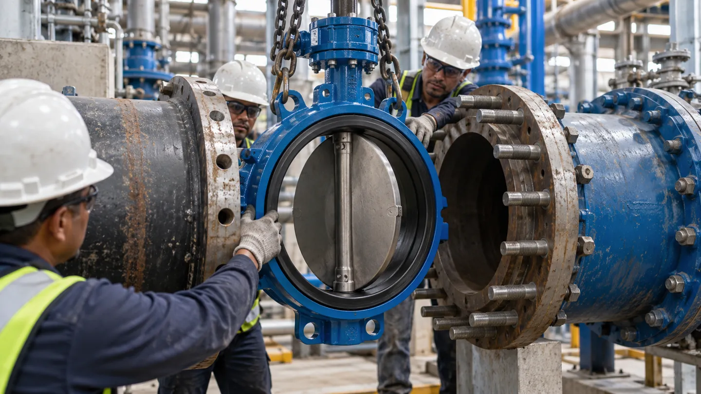
A butterfly valve controls flow with a disc that turns a quarter turn inside the body. In the open position the disc remains in the waterway, parallel to the flow; in the closed position it presses against a seat to seal. That single design fact drives every installation rule that follows. The disc always needs somewhere to swing, and the seat always needs a clean surface to close against.
Most butterfly valves carry no pipe threads and no welded ends. A wafer body sandwiches between two pipe flanges. A lug body takes studs through ear holes in its rim, and a double flanged body bolts to mating flanges like a gate valve does. The valve depends on the surrounding pipework far more than other valve families do.
Typical rubber-seated (resilient) butterfly valves live inside a modest pressure and temperature window. In the AWWA world, ratings run from 25 to 250 psi. The most common is Class 150B: 150 psi at 16 ft/s flow. Industrial PN10 and PN16 wafer bodies are the everyday equivalents, and flanged AWWA designs reach 72 inches, with wafer styles clustered in the smaller sizes
Check your line conditions against that window before the valve leaves the storeroom, not after it leaks. The three decisions that follow, connection type, orientation, and bolting, are the ones you cannot redo without shutting the line down.
Wafer, Lug, or Double Flanged: What Your Connection Type Decides
Connection type is the first real fork in the road. It decides which flanges you need and how the bolts run. It also decides whether the valve can sit at a dead end, and whether you will be able to pull it out later for service. The differences are mechanical, not cosmetic.
Wafer Body: The Default, and Its One Big Limitation
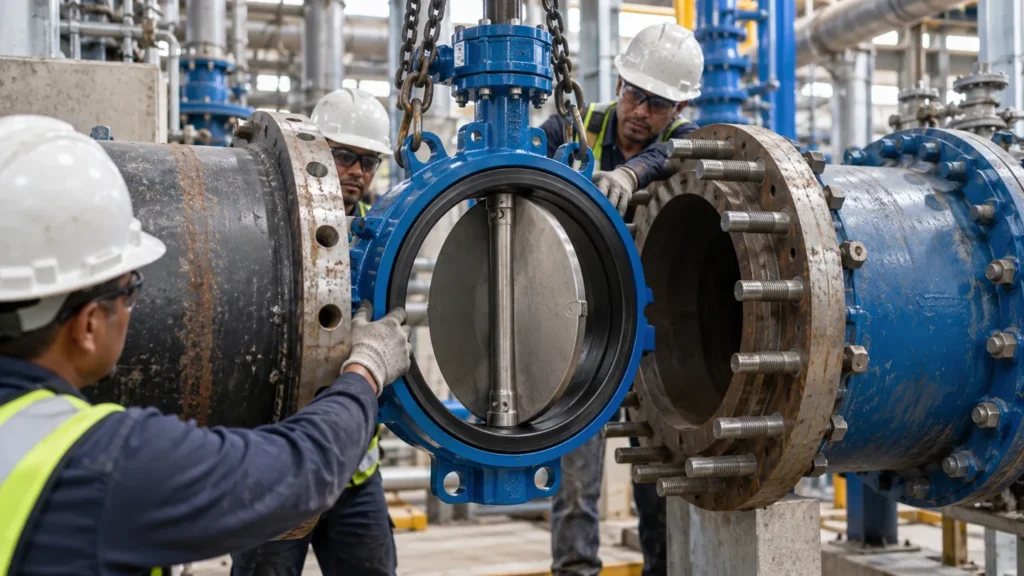
P The wafer body is the most common butterfly valve in the world, and for good reason. It is short, light, and cheap, and it centers itself between two flanges. Installation is a clamp job: slide it between the flanges, confirm the flange spacing leaves the disc free, and pull the joint together with one stud set crossing both flanges.
The limitation is symmetrical. Because the pipe flanges clamp the body, the wafer valve cannot support itself. It cannot terminate a line, and once assembled it cannot be pulled on its own. Freeing it means supporting or dismantling the adjacent line. In pipeline terms, a wafer valve installed today is a valve your future self dismantles around, not removes.
A wafer body also trusts its neighbors to hold under thrust. AWWA practice warns against installing any butterfly valve at a dead end or close to a bend without proper restraint. Without it, line thrust can blow the valve off the end of the pipe . For a wafer body, which owns no anchors of its own, that warning deserves double weight.
Lug Body: Through-Bolts, Single-Side Removal
A lug body carries threaded lugs around its rim. Each stud threads into a lug and grips one flange, so either half of the joint can be opened without disturbing the other. That is what makes the lug body the standard choice downstream of equipment that needs isolation for service: one side stays piped, the other comes off.
Two checks protect that convenience. First, bolt length. A stud that is too long bottoms out in the lug or bridges the gap, and overtightening then cracks the lug ear instead of compressing the gasket. Measure total grip length before you grab studs from the bin. Second, sealing rating. Lug and wafer bodies are often offered with a seat rating lower than the flange rating of the body. Read both numbers on the nameplate, and keep line pressure under the lower one.
Field experience shows what the second check is worth. A package skid was built around 150 class rubber-lined butterfly valves and asked to seal against 20 bar of seawater, and the seats failed in batches (Eng-Tips, 2006). The eventual fix meant ordering high-performance valves, waiting out their long deliveries, and taking a shutdown to install them.
One more nuance belongs here. Torque-seated designs, common in high-performance and triple offset bodies, seal by wedge load from the operator, not by rubber elasticity. Their gearboxes must deliver the rated seating torque. A gearbox that never quite reaches 100 percent closed leaves a valve that leaks at every cycle (Eng-Tips, 2006).
Double Flanged: When the Valve Carries Itself
A double flanged body has its own flanges, drilled and faced, and bolts to mating pipe flanges like any flanged gate valve. It carries itself and holds thrust, which suits the jobs wafer and lug bodies step back from: large bore, buried or municipal lines, and pump discharge with real hydraulic disturbance. The cost is length and weight, plus a second gasket pair to maintain. In return, the valve tolerates imperfect neighbors better than a wafer body ever will.
The matrix below lines the three bodies up against the decisions you actually make at the site.
Connection Type Decision Matrix
| Connection type | Typical service | What changes during installation | Where it fails |
|---|---|---|---|
| Wafer (P default) | HVAC, water utilities, general process isolation, compact spaces | Sandwiched between flanges, self-centering, one stud set crosses both flanges | Cannot terminate a line, cannot be removed alone once assembled, weak against thrust at dead ends or near bends |
| Lug | Equipment isolation, serviceable branches, dead-end duty with verification | Studs thread each side independently, one side can open while the other stays piped | Seat rating often below body flange rating, overlong studs crack lug ears |
| Double flanged | Large bore, buried or municipal lines, pump discharge, high disturbance | Bolts like a flanged gate valve, two gasket pairs, valve supports itself | Heavier, longer lay length, second gasket set to maintain |
| Grooved | Quick-build skids, temporary and modular lines | Couplings grip grooved ends, fast assembly | Pressure and temperature capped by coupling and groove spec, niche availability |
A wafer valve exists because two flanges clamp it, and once the line is assembled it is the one valve you cannot remove on its own for service.
Carry that sentence into procurement. The price gap between a wafer and a lug body is measured in minutes of fitting work. The gap between the right and wrong choice is measured in a shutdown, an excavation, or a redesigned branch.
The Installation Sequence, Step by Step
With the connection type settled, installation itself is a short chain of steps, each with one judgment that separates a clean joint from a callback. Work them in order; each step assumes the one before it.
- 1Inspect: flange faces, seat, disc
- 2Position: align flanges, leave the disc free
- 3Disc and gaskets: pick the disc state for the seat design
- 4Bolt: star pattern, measured stud length
- 5Prove: cycle, then pressure test within rating
Step 1: Inspect before the valve leaves the ground. Wipe the flange faces, seat, and disc clean, then cycle the valve once and watch the stops or limit switches deliver a full close. Grit left over from storage does most of its damage on the first stroke.
Step 2: Position without forcing. Align the mating flanges and spread them far enough apart that the body, and any molded liner, is not scraped or dislodged on the way in. Never pull pipe to valve with bolts. Deflecting the pipe to close the joint twists the body and ruins the seal, and the fault grows with valve size.
Step 3: Set the disc, and settle gaskets by seat design. Published advice disagrees on disc position during assembly, and the disagreement has a real cause. Municipal rubber-seat practice calls for the valve closed before installation. Wafer-and-liner guides favor a slightly open disc held just inside the sealing face. Actuated HVAC bodies are usually set nearly closed so the disc cannot snag a flange. Follow the seat design in your hands. A molded-in liner lives and dies by not being scraped. A replaceable seat tolerates a closed disc. A torque-seated body must reach its seat under the operator, not under your hands. Gaskets follow the same logic. An integrally molded liner needs no separate flange gasket. A body with a replaceable seat seals on the gasket, so fit the gasket the schedule calls for.
Step 4: Bolt in a star pattern with measured studs. Snug every bolt by hand first. Then tighten across the joint in a star pattern, repeating the crossing passes instead of crushing one side; as many as five passes is accepted municipal practice for even stress. Confirm the disc swings free through full travel before final torque. Stud length must match the grip of both flanges plus the body, with a nut fully engaged at each end and no thread bottoming in a lug.
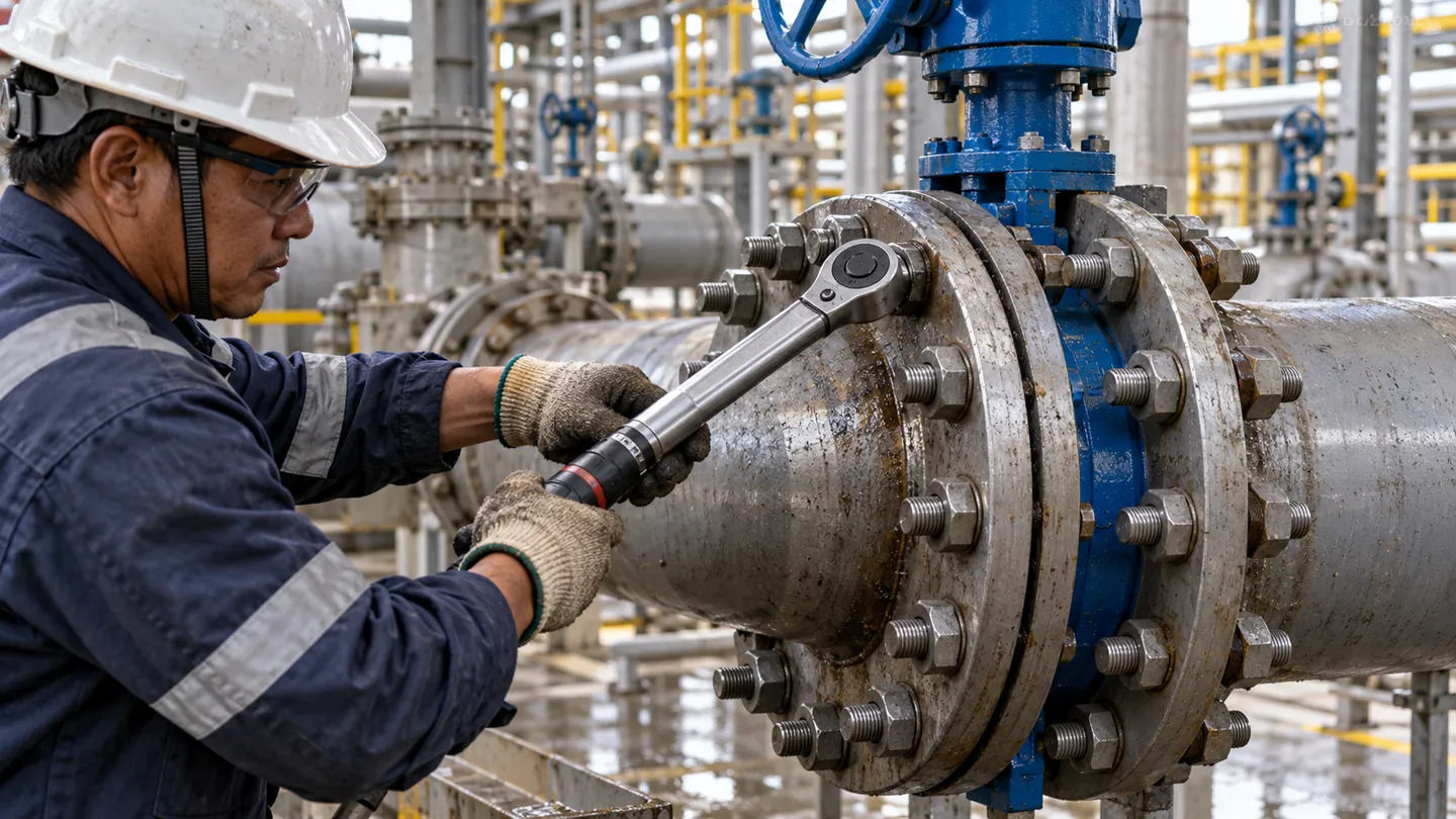
Step 5: Prove the joint before you leave it. Cycle the valve through a full open-close stroke and watch the disc clear both flange bores. One clearance deserves a second look. With thick-wall or plastic-lined pipe, the open disc reaches into the mating pipe. An undersized bore can stop it part way, crack the seat, and leave a valve that leaks closed . Then flush the line and pressure test, because debris left in new pipe is a leading cause of valve leakage during testing . Hold the test at or below the seat rating, which is what the seal was actually built to meet.
If the connection type for your duty is still open, Vincer builds wafer, lug, and double flanged bodies with matched actuation.
Request a Valve QuoteOrientation and Flow Direction: The Decisions You Cannot Undo
Everything so far can be fixed by reopening the joint. Orientation and flow direction are different. Once the line runs, an orientation error announces itself as condensation in electronics, a valve that will not seat, or an actuator that stalls. Every one of those costs a shutdown to revisit.
Stem and Actuator Orientation
Textbook answers say a butterfly valve mounts at any angle, and for a clean manual valve in friendly service, that is true. Engineering practice narrows it fast, and three rules carry most of the weight.
First, never point an actuator or gearbox straight down. Actuator makers forbid the attitude because condensation and seal weep drip straight into the electronics and the packing (Reddit r/MechanicalEngineering, 2020). The same rule shows up from the storage side: valves with electric operators in storage need their electronics protected against condensation from temperature swings. A disc pointed down also hangs its weight on the shaft thrust bearing, which is sized for pressure load, not gravity.
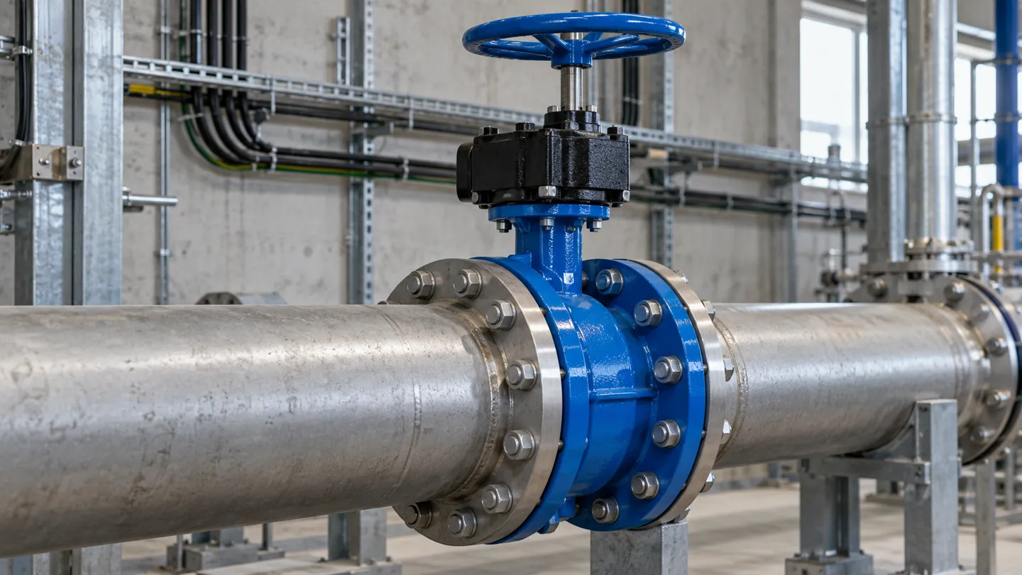
Second, prefer a horizontal stem on larger valves and on dirty services. The disc weight then rides the shaft bushings instead of the thrust face, and debris does not settle into the seat pocket.
Third, think about the next maintenance. Seat-side access is worth arranging at installation time, because some AWWA designs allow an in-line seat change only if the crew can reach the seat side.
An actuator or gear housing pointed straight down collects condensation on its electronics and loads the disc weight onto the thrust bearing. Both failures stay invisible until the first heavy rain cycle or the first emergency close.
Flow Direction and Dynamic Torque
Most resilient-seated butterfly valves seal in both directions, and AWWA bodies are rated for flow either way. The arrow on the body is still not decoration. It marks the direction for which the seat, the disc stop, and the published torque curve were set. Dynamic torque, the hydraulic load that peaks as the disc travels, is one of the first factors an engineering installation guide tells you to settle. Fit the valve against its rated direction and the actuator you sized on paper may lack the margin to break the disc loose at differential. That fault shows up as a stalled operator at the worst possible moment.
Neighbors matter as much as arrows. Turbulence from a fitting directly upstream causes disc flutter and bearing wear. Dead-end and bend locations put the valve in the thrust path, which is why restraint there is a specification item, not a suggestion. Closing speed belongs to the same conversation. A quarter-turn lever can slam a valve shut fast enough to surge the line. Levers stay on small, low-energy lines; slower operators take everything else.
One operator rule closes the loop. Never remove a gearbox or actuator with the line under flow or pressure. The disc becomes a closed damper the flow can slam, and the operator is what holds the shaft seals in place.
Orientation Rules at a Glance
Orientation Decisions and Their Failure Modes
| Orientation choice | Works best when | Fails when |
|---|---|---|
| Stem vertical up, actuator up | Clean fluids, small to mid valves, cramped headers | Condensation or media can pool on the closed disc in dirty service |
| Stem horizontal | Large valves, solids-bearing or municipal service, buried boxes | Needs clearance for the operator, disc weight rides the bushings by design |
| Actuator or gear down | Nowhere; treat as prohibited | Condensation enters electronics, packing weeps by gravity, disc weight loads the thrust bearing |
| Flow with the body arrow | Default for every valve | Reversed flow loads the seat and eats actuator torque margin |
When a Freshly Installed Butterfly Valve Misbehaves
Most butterfly valve problems that surface in the first year of service trace back to installation day. The list below runs in the order maintenance crews usually meet it, and every line starts with the cheapest check.
Sticky or half-travel operation, especially at the end of every cycle, rarely means a broken valve. On an actuated line it usually means the limit and torque switches were never set to reach a full close, or process residue is building on the seat. One reported case, a 12 inch triple eccentric valve sticking at the end of each regeneration cycle, came back to switch adjustment and steam-borne residue (Eng-Tips, 2018). The valve itself was fine. Reset the switches against the actual closed disc before you order parts.
Batch seat failures and persistent internal leakage point at a rating mismatch, not bad luck. Check the seat rating against real line pressure, including transients and vacuum. Resilient seats routinely carry a lower sealing pressure than the body flange rating, and pressure surges or vacuum can finish what overpressure starts (Eng-Tips, 2006). When a purchase document needs a number, name a recognized seat test instead of the words “bubble tight”. The right test presses the valve above its rating and allows no visible leak from resilient seats (Eng-Tips, 2006).
Flange face weeping usually starts at the sealing surfaces, rarely inside the valve. Pull the joint, inspect both faces for gouges and score paths, and refinish them before reassembly. Installers who traced this fault report wire-brushing and re-facing as the fix (Reddit r/HVAC, 2025). A valve parked half open wears the same way, because butterfly bodies are not built to regulate. Prolonged operation below about 20 degrees open is outside their design.
- Cycle symptom: check limit and torque switch settings first, then residue.
- Leak past seat: compare seat rating to line pressure and transients.
- Flange weep: inspect and refinish flange faces.
- Hard to turn: check packing, disc clearance in mating pipe, and operator stops.
- Any actuated fault: confirm flow direction matches the body arrow before re-sizing the actuator
Writing Installation Specs That Prevent Rework
Every failure above has a paper trail that starts before the order does. The seat mismatch that ended in long-delivery replacements was a specification error. So were the lug studs cracked by whatever was in the bin and the disc stopped by an undersized pipe bore. Each would have cost one line in a spec to prevent. Rework, by contrast, is a shutdown, an excavation, or a rental bypass.
Three checks carry most of that prevention, and all three cost nothing at bid time. First, connection type by duty. Specify lug or double flanged bodies at dead ends, at equipment needing single-side isolation, and at pump discharge where thrust and turbulence live. Reserve wafer for joints that will never need single-side removal. Second, ratings in writing. Put the seat rating, not just the body class, into the purchase line, and hold it against line design pressure including transients. Third, actuation as a system. Confirm flow direction and operating torque against the actuator size, and keep valve and actuator on one mounting interface so the pairing arrives matched.
Three checkpoints for the specification
- 1Connection type by duty: lug or double flanged at dead ends, single-side isolation branches, and pump discharge; wafer only where the joint never needs removal.
- 2Seat rating in writing: hold it against line design pressure including transients, not just the body class.
- 3Actuation as a system: one mounting interface, torque matched, travel stops set, flow direction confirmed.
That last check is a procurement habit as much as an engineering one. A valve ordered with its actuator from one source arrives with the torque matched and the travel stops set. A valve and actuator ordered separately arrive as two puzzles for the site crew. VINCER‘s catalog is online if you want to check a wafer, lug, or double flanged valve and its 50 to 4,000 Nm actuator range against your installation checklist.
Get the Valve and Actuator Matched Before the Order
Send your line conditions and Vincer replies with a wafer, lug, or double flanged package and actuation sized from 50 to 4,000 Nm.
Start Your InquiryReferences
- Eng-Tips. “Rubber Lined Butterfly Valve Failures.” 2006. https://www.eng-tips.com/threads/rubber-lined-butterfly-valve-failures.147087/
- Eng-Tips. “12” Butterfly Sticky Issue.” 2018. https://www.eng-tips.com/threads/12-quot-butterfly-sticky-issue.438927/
- Reddit r/MechanicalEngineering. “Why Cannot Install Butterfly Valves Downwards?” 2020. https://www.reddit.com/r/MechanicalEngineering/comments/f1n2pk/why_cannot_install_butterfly_valves_downwards/
- Reddit r/HVAC. “Butterfly Valve Flange Leaking.” 2025. https://www.reddit.com/r/HVAC/comments/1ql15tm/butterfly_valve_flange_leaking/