What a Check Valve Does: Flow Direction and Where It Goes
A booster pump that behaves all morning can wreck itself in one power cut. When the motor stops, the column of water sitting in the discharge line reverses, spins the pump backwards, and can knock the impeller loose. The only part standing between a normal stop and that failure is a single disc that swings shut. That is all a check valve is: a one-way door for the pipe. The catch is that the door only works when it points the right way, sits in the right place, and uses a mechanism that matches how the pipe runs.
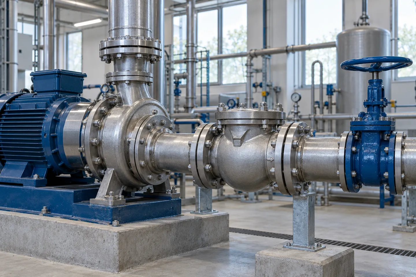
Inside the body, one moving part responds to pressure. Forward flow pushes the disc open. When forward pressure drops, a spring, gravity, or the backflow itself returns the disc to its seat before the reverse surge builds. There is no handle and no actuator, nothing to adjust after the fact. Installation is the only setting the valve will ever get, and the flow arrow cast or stamped on the body is the first thing to read. Pipe flow and arrow must point the same way before a single bolt goes in.
Pointed the wrong way, the valve fails in one of two directions. If the disc cannot open, the line goes dead: the pump runs against a closed door, overheats, and cavitates. If the disc never seats, the line backflows on every shutdown and the pump water-hammers on every restart. Neither fault shows up during installation. Both show up weeks later, which is why the arrow check happens before mounting, not during troubleshooting.
Location follows the same logic. The valve belongs on the discharge side of the pump, where it blocks reverse flow back into the pump. On the suction side it adds permanent friction loss to the pump inlet and becomes a cavitation risk. Residential systems follow the same rule at smaller scale. A sump pump check valve sits on the vertical discharge run just above the pump, below floor level, so the water above it cannot fall back into the pit.
One term to set aside before going further. In irrigation work, a double check valve assembly is a backflow-prevention device built from two valves plus shutoffs and test ports, and it exists to protect the potable supply. Everything in this article is about the single check valve inside a pump or process line. The two are not interchangeable.
Check Valve Designs and What Each Allows: Orientation First
Every check valve does the same job, but the mechanisms differ, and the mechanism decides what the pipe is allowed to do to it. Orientation is the clearest example: it is a mechanical constraint, not an installer preference. A design that closes by gravity cannot be asked to close uphill. The three structures below cover most industrial installations. Each one pairs the mechanism with the attitudes it tolerates and with the failure path that appears when those attitudes are ignored.
Swing check valves
A swing check valve has a disc hinged at the top of the bore. Forward flow swings it open; gravity and reverse flow swing it shut. With no spring to help, the disc needs stable, mostly horizontal flow to behave. It runs well in horizontal lines and in vertical lines where flow goes up. In a vertical line with downward flow it fails by design: the disc hangs open, flow reverses, and the late slam arrives with the full column behind it. Turbulence is the quieter killer. An elbow or a pump discharge close upstream throws unsteady flow at the swinging disc, the disc chatters, and the pin and seat wear long before their time. Among the common designs, swing checks are the most sensitive to straight run.
Lift check valves
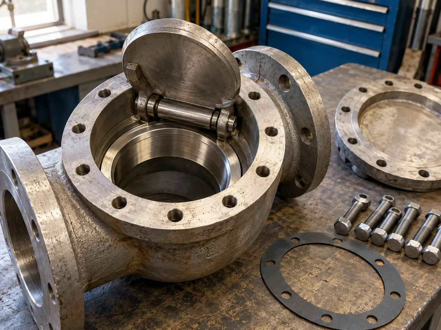
A lift check valve moves its disc axially along a guided seat. Forward pressure lifts the disc; gravity drops it back. The guide has to sit vertical for gravity to work, so this is horizontal-line equipment. Bolted into a vertical run, the disc either jams in the guide or seats off-center and leaks. The trade for that strictness is sealing quality: short guided travel gives a cleaner seat than a swinging disc, at the price of higher flow resistance. Some flanged lift versions add a screw-down handwheel, which lets the same body act as an emergency isolating valve during commissioning.
Dual-plate wafer check valves
A dual-plate valve splits the disc into two half-plates on a center hinge, each held by a torsion spring. The springs start closing the plates the moment forward flow slows, so the plates reach their seats before the reverse surge builds. That early closing is why dual-plate valves are the default answer to water hammer in retrofit work. The wafer body clamps between two flanges, the shortest face-to-face arrangement in the line, and the springs close the plates in any attitude. That makes dual-plate the most orientation-tolerant design here. Even so, anything beyond horizontal and vertical-up deserves a written confirmation from the manufacturer, because spring strength varies with size.
Two further designs complete the map. Axial, or silent, check valves carry a spring-loaded disc on the pipe centerline. They close fastest of all and tolerate the worst flow conditions, which is why pump stations specify them close to the discharge. Ball check valves pass solids and slurries that would jam a disc, trading tight shutoff for that tolerance.
Check valve designs vs installation rules
| Design | Closure mechanism | Attitudes that work | Straight-run sensitivity | Failure path when misapplied | Confirm before install |
|---|---|---|---|---|---|
| Swing | hinged disc, gravity closes | horizontal, vertical with flow up | high | disc hangs open in downflow, chatter wears pin and seat | straight-run distance upstream |
| Lift | guided disc, gravity closes | horizontal only | medium-high | disc jams off-guide in vertical runs | guide axis sits vertical |
| Dual-plate wafer | two spring-assisted half-plates | any attitude, extremes confirmed | low-medium | chronic flutter fatigues springs | spring spec against real flow |
| Axial (silent) | spring-loaded centerline disc | any attitude | low | seat wear when flow never fully opens | cracking pressure vs minimum flow |
| Ball | free ball lifted by flow | any attitude per design | low | seat leakage in clean low-flow service | media solids match |
None of these attitude limits is a preference. Each follows from where gravity and springs sit inside the mechanism. When the attitude you need does not appear in the manufacturer’s documentation, the check to run is not a trial fit. It is a written question.
Installing a Check Valve: Steps, Sealing and Site Checks
With the design picked and the arrow read, installation is a short chain of steps. Each step exists because skipping it ends in a documented failure.
- Isolate and drain. Shut the pump down, lock out the power, depressurize the line, and drain the section. A joint opened under residual head discharges without warning.
- Re-verify direction and attitude on site. Hold the body arrow against the real flow direction, not against the drawing, and check the installed attitude against the design rules above. Site piping drifts from drawings often enough that this step catches genuine errors before they become weeks-later mysteries.
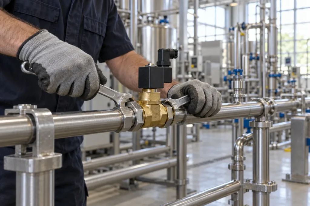
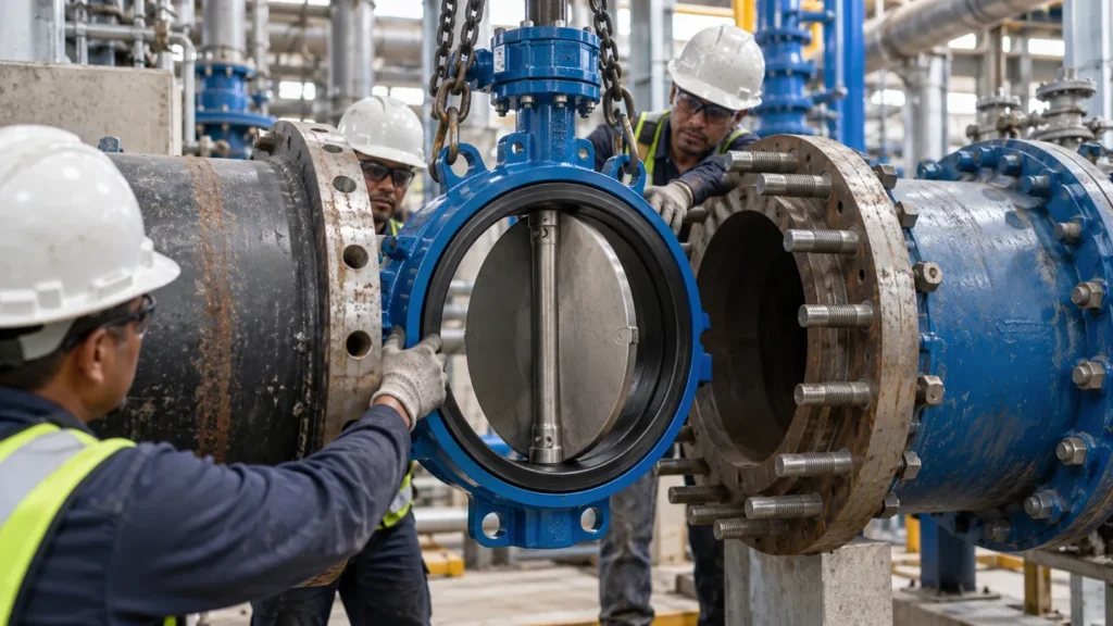
- Make the joint. Threaded ends take seal tape wrapped with the rotation, so tightening does not unwind it. Flanged ends need clean faces, a centered gasket, and bolts tightened in a cross pattern over several passes. Wafer bodies need both flanges aligned on a common axis with the valve centered between them; uneven bolting distorts the body, and the seat distorts with it.
- Treat welded seats with respect. Where the valve will be welded into the line, soft-seated designs must have the seat and disc removed first. Welding heat destroys elastomer seats in place, and a metal-seated valve still follows the manufacturer’s welding procedure to keep heat from distorting the seat.
- Flush, then test. Flush the line before first startup so weld slag and debris never reach the disc or seat. Then pressure-test and check for reverse leakage. A valve that holds forward pressure but weeps backwards will not hold a shutdown.

Three failures in this chain are self-inflicted: a soft seat welded in place, a startup without flushing, and a wafer body pulled out of round by uneven bolts. All three are checkable on site in less time than the rework takes.
The steps above decide most of a check valve’s service life: get attitude limits, straight-run advice and sizing data from VINCER in writing.
Ask VINCER About Your LineWhere It Belongs: Pump Discharge Distance and Straight-Run Rules
System position comes before straight run. The order matters in both directions. The isolating valve lets maintenance happen without draining the system, and the check valve shields the pump from whatever the line does after a stop. The suction side takes no check valve at all, because the friction loss and cavitation risk outweigh any benefit there.
Distance from the pump is where written rules stop agreeing, and the disagreement is worth seeing before it turns into a site argument.
Straight-run advice by source
| Source | Recommended distance | Applies to | Nature of guidance |
|---|---|---|---|
| Manufacturer installation guides (DFT) | install just after the pump discharge, keep about 5 diameters of straight pipe | swing and dual-plate in typical service | manufacturer field guidance |
| MSS standard practice, as cited by Valve Magazine | at least 10 diameters downstream of pumps, tees and fittings, 5 from elbows | general, strictest for swing discs | industry standard practice |
| Velan service manual, as quoted on Eng-Tips | at least 10 diameters from upstream pumps, elbows and fittings | piston, ball and swing types | manufacturer manual |
| Engineering forum practice | 3 x DN behind the discharge, never on 90-degree elbows | centrifugal pump discharge | practitioner consensus, disputed in the same thread |
| Close-coupled on the discharge flange | possible, some skid packages ship this way | axial designs or after manufacturer review | exception path |
The numbers disagree because the damage profile differs by structure. Turbulent flow off a pump or an elbow moves a swinging disc the most, so swing checks draw the strictest distances. Spring-loaded axial designs hold their disc on the centerline and shrug off the same turbulence. Read the table by structure and most of the conflict resolves. Treat 10 diameters as the conservative default for swing discs, and accept shorter runs for spring-loaded designs. When a compact skid leaves no room, replace the argument with a written answer from the valve manufacturer. (Eng-Tips, 2008; Valve Magazine, 2023)
The useful trend is that the distance value is a specification-stage decision. Settled at the drawing stage it costs nothing. Discovered at commissioning it costs a cut line, a re-weld and a retest, and that is exactly how the erosion cases below happen.
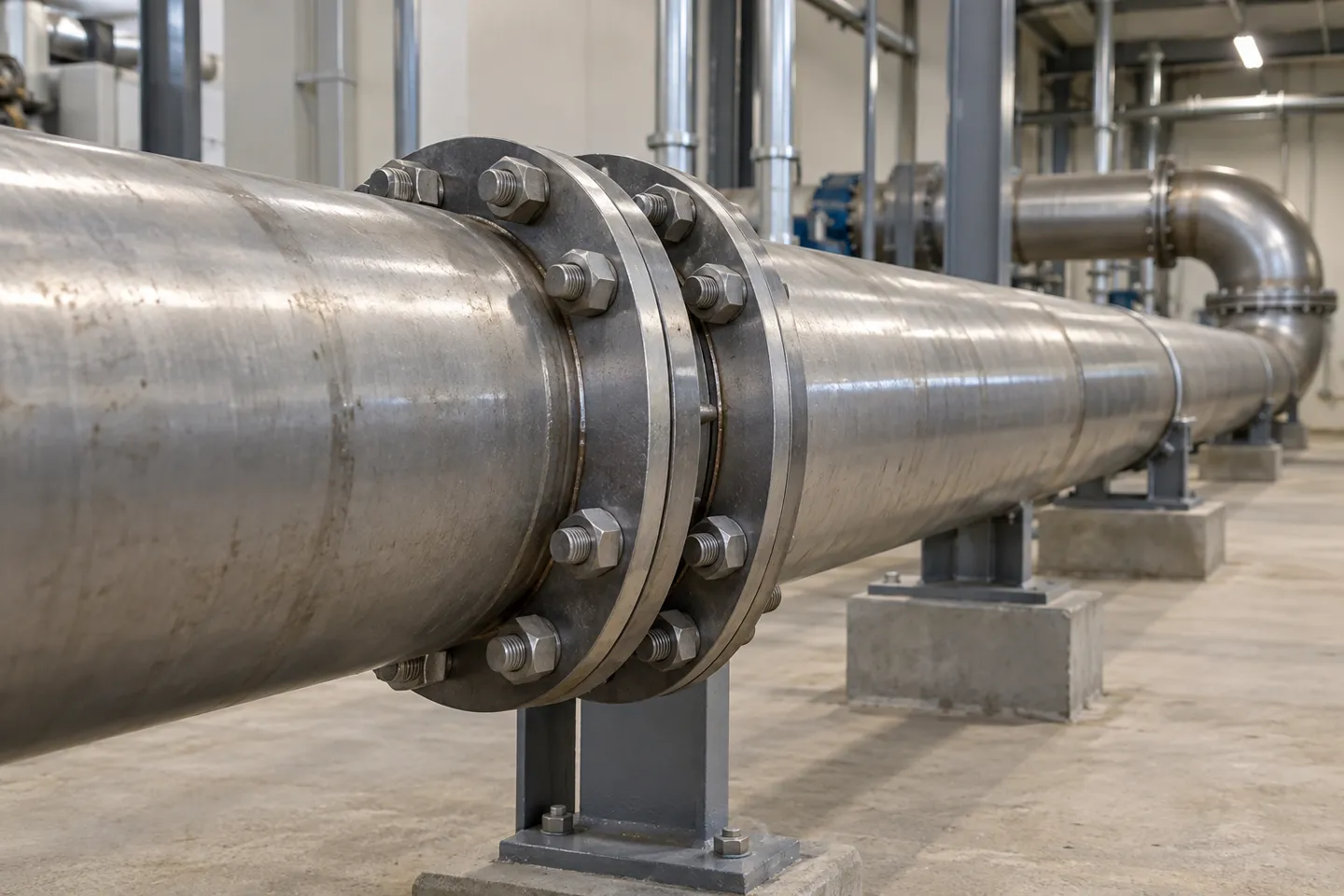
Two positions are never fine. Directly behind an increaser, the jet scrubs the disc and pin until the valve stops seating. On the suction side, the valve starves the pump it was meant to protect.
Sizing and Spec Parameters Before You Order
Sizing decides valve life more quietly than anything in the steps above, and it happens in the office, before the order exists.
Line size is not valve size
A check valve sized to the pipe instead of the flow runs partly open for its whole life, and a partly open disc flutters. Flutter wears the pin, the hinge and the seat edge until the disc stops seating at all.
Documented case: sized for future capacity
17°
Sized one size up for a planned future capacity, a swing check valve ran at only 17 degrees open. Its disc wobbled, and the pin wore through until the disc came loose. Source: Valve Magazine, 2023.
The same report lists oversized valves as the most common single cause its authors encounter. DFT’s installation guide says the same from the workshop side, attributing most check valve maintenance problems to application and sizing errors. The working rule among engineers is one pipe size below line size for conventional designs, verified against the manufacturer’s flow data. Treat it as a rule of thumb rather than a standard; the verification is the part that matters. Low-flow lines need the same check on cracking pressure, because a valve that never fully opens fails by exactly this chain.
Pressure, temperature and connection standard
Pressure class and temperature follow the system, not the vendor’s largest number. Class and PN ratings come off the design sheet. Temperature decides the seat family, soft or metal, and with it the welding practice from the installation steps. The connection standard must match the line’s flanges, and on export projects that means confirming ANSI, GB, DIN or JIS explicitly instead of assuming.
Published industrial ranges give a sense of scale. Wafer dual-plate bodies run from DN15 to DN300 at pressures up to around 40 bar. Flanged swing checks reach DN600, with metal-seated versions rated for services up to around 425 degC. Flanged lift checks cluster around 16 bar. Treat these as catalog-scale references and verify against the actual manufacturer’s tables, because seat material and pressure class move every one of those numbers.
The four installation boundaries to put in the inquiry
Every failure path above starts with a decision that could have been made at the quotation stage. That makes the inquiry the cheapest place to spend four questions. One: allowed attitudes, in writing, for the exact model. Two: recommended straight run for the real layout, including what is acceptable inside a tight skid. Three: sizing data for the real duty, cracking pressure and flow data, not just the nominal diameter. Four: welding and commissioning practice for the seat family being bought, seat removal and flushing included. A supplier who answers these four in writing is managing installation risk. One who answers in adjectives is selling a pressure class.
Inquiry checklist: four installation boundaries
- Attitude range confirmed in writing for the exact model
- Straight-run advice tied to the actual layout, including skid limits
- Cracking pressure and flow data for the real duty, not just DN
- Welding, seat-removal and flushing practice stated for the seat family
What This Means for Your Next Check Valve Order
Read as a set, the failures above share one property: each was determined before startup. The 17-degree disc was set by an order line. The eroded pin was set by a skid layout. The hung-open swing disc was set by a drawing that showed a vertical down-run. Manufacturer field data says the same thing in aggregate, tracing most check valve maintenance problems back to application, sizing and installation choices. None of that makes the valve a bad product. It makes the purchase conversation the cheapest place to prevent the failure.
For project engineers the practical version is short. Move the four boundaries from site reasoning into the inquiry, and ask each bidder to answer them in writing against your actual layout. The cost is four lines in a specification. The avoided cost is cutting a finished line apart at commissioning, or a disc that arrives loose after two years of flutter. The written answers also separate suppliers faster than another page of pressure classes.
Spec-stage self-check
- Does our spec template carry the four installation boundaries?
- Do bidders answer them in writing against our layout?
- Is straight-run advice tied to our structure choice, not copied generic?
For distributors and wholesalers the same material becomes counter advice. Attitude and distance answers go by structure, not by brand. Stock logic follows the published ranges as well. Wafer dual-plate in DN15-DN300 covers the mainstream of tight retrofit lines, while flanged swing checks carry the large-bore and high-temperature end toward DN600. A counter that answers the attitude question from the mechanism, as the table above does, keeps trade customers off the returns path.
If this checklist needs a supplier who answers it in writing, that is how we work at VINCER. Our wafer check valves come in swing, lift and dual-plate structures covering DN15-DN300 at up to 40 bar. Flanged swing and lift bodies extend the line to DN600 and into high-temperature service. We return attitude limits, straight-run advice and cracking-pressure data against your actual line, in ANSI, GB, DIN or JIS flange systems, and the wafer check valve range is where that comparison starts.
Put the Four Boundaries Into Your Next Inquiry
Four written answers, against your actual layout: attitude range, straight run, sizing data and welding practice.
Request Written Answers from VINCERReferences
- Valve Magazine. “Check Valve Installation Considerations to Maximize Process Performance.” 2023. https://valvemagazine.com/articles/check-valve-installation-considerations-to-maximize-process-performance/
- Eng-Tips. “Check valve installation procedure.” 2008. https://www.eng-tips.com/threads/check-valve-installation-procedure.212528/