Introduction
In heavy industries like petrochemical processing, LNG transport, and offshore desalination, reliable quarter-turn valve automation is a critical safety imperative. Engineers face extreme differential pressures, highly corrosive media, and severe static friction. Standard gear-driven linear actuators often fail under these conditions, making a robust scotch yoke actuator the definitive, heavy-duty mechanical solution for industrial flow control systems.
The Core Challenge of Quarter-Turn Valve Actuation
To truly comprehend the engineering superiority of this specific sliding-block mechanism, it is essential to first dissect the invisible physical and hydrodynamic forces it must continuously overcome. When automating heavy-duty pipeline infrastructure—such as pipelines built to API 6D specifications—the mechanical demands placed on the actuation system extend far beyond simple rotational movement. The primary adversaries in fluid dynamics and valve operation are Stiction (Static Friction), dynamic bearing friction, hydrodynamic torque, and immense Differential Pressure (ΔP) which can often exceed 150 bar in mainline applications.
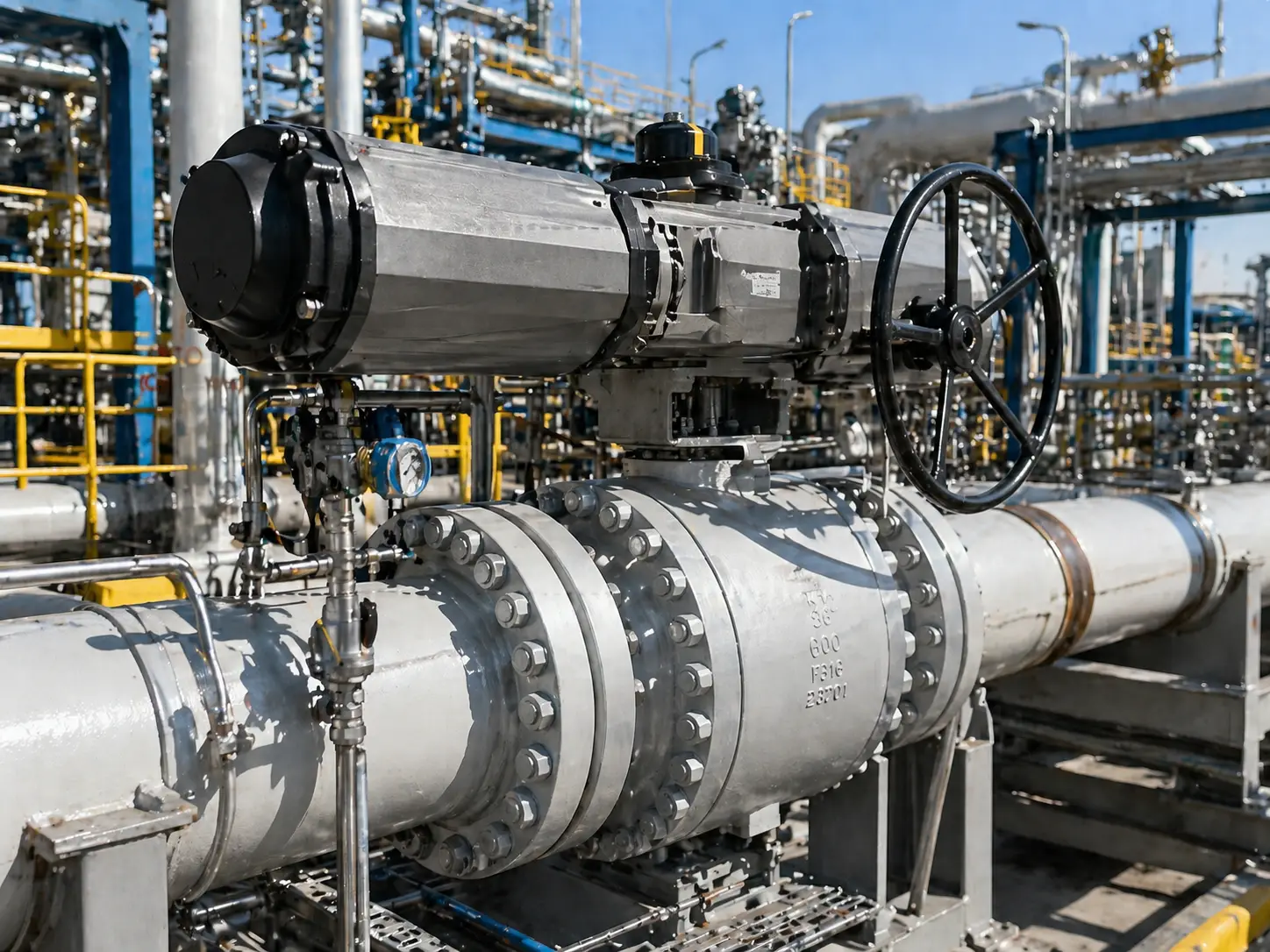
Consider a massive 24-inch Class 600 trunnion-mounted ball valve installed in a mainline crude oil pipeline or a high-pressure seawater desalination intake. During standard operational cycles, this valve might remain in a fully open or fully closed state for several consecutive months, serving purely as an emergency isolation node. Over this extended stationary period, the polymeric seat materials—such as virgin Polytetrafluoroethylene (PTFE), Polyether ether ketone (PEEK), or reinforced elastomer composites (like Devlon)—undergo a thermodynamic and mechanical phenomenon known as “cold flow” or elastomeric creep.
Under continuous line pressure, these polymers microscopically migrate and compress into the porous micro-structure of the metallic ball’s surface. Concurrently, the upstream fluid pressure exerts tens of thousands of pounds of lateral force, pinning the ball aggressively against the downstream sealing mechanism. This creates a massive mechanical interlocking effect between the ball and the seats. The initial rotational force required to shatter this static grip, overcome the seat interference, and unseat the ball is scientifically referred to as the Break to Open (BTO) torque. If an actuator cannot deliver a sudden, disproportionately high spike of torque at exactly the 0-degree position, the valve will simply remain seized, triggering a cascading failure throughout the process control system and potentially causing severe over-pressurization upstream.
The “Stalled Truck” Engineering Metaphor
Think of this heavily seized valve as a massive, fully-loaded truck stalled on a steep incline. The initial mechanical thrust required to break the tire’s static grip on the road and get the wheels turning from a dead stop is astronomical. However, once the truck begins rolling, kinetic momentum takes over, and the continuous force required to keep it moving drops significantly. This represents the “Run Torque.”
In valve automation, this translates directly to the massive difference between BTO torque and Run torque. The Run torque is typically only 30% to 40% of the initial BTO requirement. Sizing a standard linear-torque gear unit to meet an extreme BTO requirement results in an actuator that is grossly oversized, excessively expensive, and consumes completely unnecessary amounts of compressed air during the entire 90-degree stroke. The industry required a mechanical linkage that mathematically concentrated its maximum mechanical advantage precisely where the pipeline needed it most.
Anatomy and Kinematics of the Scotch Yoke Actuator
The mechanical brilliance of the scotch yoke pneumatic actuator lies in its non-linear conversion of linear thrust into rotational torque. Unlike rack and pinion designs that rely on the continuous engagement of fragile gear teeth, this actuator utilizes a sliding mechanical linkage specifically engineered to absorb and transmit extreme stress without premature wear, metal fatigue, or galling.
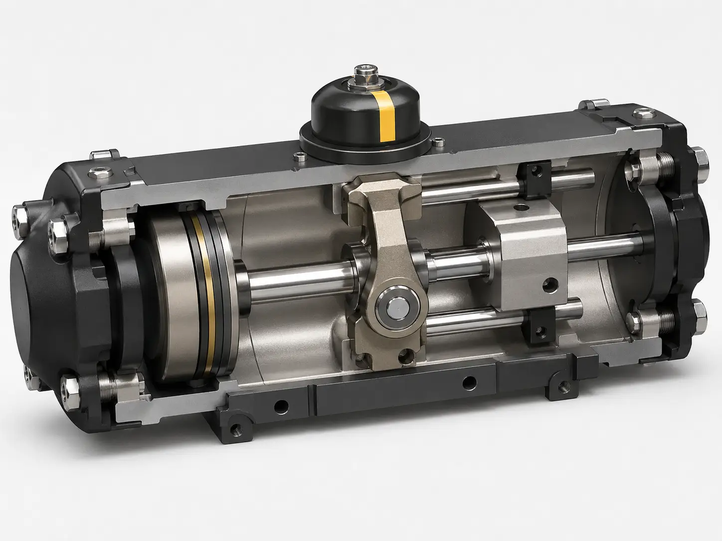
The Mechanical Core: Pistons, Sliding Blocks, and Yokes
By examining the internal architecture of a heavy-duty unit, we can precisely identify the highly engineered components governing this kinetic energy transfer. Each element is metallurgically selected to endure millions of cycles:
- The Power Cylinder: Driven by compressed instrument air or hydraulic fluid, this precision-honed cylinder generates pure linear thrust. The internal walls are critically treated with Electroless Nickel Plating (ENP) to a thickness of at least 25 microns, or hard anodized. This creates a glass-like surface finish with an extremely low Ra (roughness average) value, which prevents corrosion from moisture in the air supply and minimizes dynamic seal friction, vastly extending O-ring lifespan.
- The Piston and Rod Assembly: The piston is fitted with specialized dynamic seals—typically Nitrile Butadiene Rubber (NBR) for standard -20°C to +80°C applications, or Fluorocarbon (Viton) and Silicone composites for extreme high/low-temperature environments—to prevent pneumatic bypass leakage. The high-tensile carbon steel piston rod transfers the linear thrust forward into the central housing without buckling under immense pressure.
- The Sliding Block and Guide Bar: This is a critical point of failure in low-quality designs. A premium actuator utilizes a heavy-duty, hard-chrome plated guide bar to absorb destructive lateral side-loads. The sliding block (or roller bearing), usually machined from high-strength self-lubricating bronze alloys (such as C93200), travels linearly along this guide while engaging the slot of the central yoke. By absorbing the radial forces generated during rotation, this mechanism prevents transverse forces from degrading the piston rod seals, ensuring zero leakage over time.
- The Actuator Yoke: The central rotating hub is typically investment-cast from ductile iron (e.g., ASTM A536) or forged from carbon steel for ultra-high-torque applications. It attaches directly to the valve stem. As the sliding block pushes against the internal slot of the yoke, it forces a smooth 90-degree rotational movement.
Decoding the U-Shaped Torque Curve
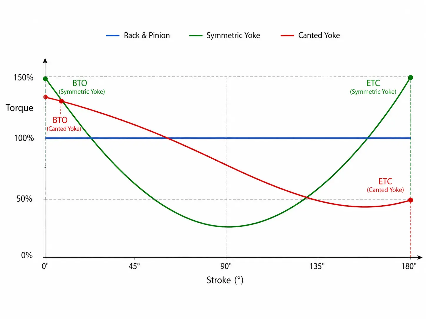
In mechanical engineering kinematics, Torque (τ) is the cross product of Force (F) and the Moment Arm distance (r). In this specific mechanism, while the pneumatic cylinder pushes with a constant linear force (assuming a steady air supply pressure), the angle between the sliding block and the yoke slot changes continuously throughout the 90-degree stroke. Consequently, the length of the effective moment arm changes dynamically, generating a highly distinctive U-shaped torque curve.
Understanding the three critical points on this mathematical curve is absolutely mandatory for proper actuator sizing to prevent stem shearing:
- Break to Open (BTO) / 0 Degrees: The valve is fully closed against maximum line pressure, and stiction is at its absolute peak. In this specific geometry, the moment arm of the yoke is at its maximum effective length. The actuator delivers an explosive, maximum torque spike, successfully shearing the ball away from the polymeric seats without requiring an oversized pneumatic cylinder.
- Run Torque / 45 Degrees: As the valve rotates towards the midway point, the ball cavity is exposed, and fluid begins to flow. The physical resistance and differential pressure drop dramatically. Correspondingly, the geometry of the sliding yoke reduces the moment arm to its shortest length, dropping the torque output to its lowest point (the bottom of the “U”). This mechanical trait ensures compressed air is not wasted and the stroke speed remains highly consistent.
- End to Close (ETC) / 90 Degrees: As the valve completes its quarter-turn stroke to reseal the pipeline, the ball must squeeze back into the polymeric seats against the full velocity of the flowing fluid. The yoke’s moment arm elongates again, providing a secondary peak in torque output to ensure a bubble-tight, leak-proof shutoff that complies with rigorous API 598 leakage testing standards.
Yoke Geometry: Symmetric vs. Canted Designs
While understanding the standard U-shaped torque curve is foundational, advanced pipeline automation requires fine-tuning that output to perfectly match the distinct torque signatures of different valve types. Manufacturers achieve this by fundamentally altering the geometric machining of the yoke pin track, categorizing the mechanisms into two primary families: Symmetric and Canted. Incorrect specification here will lead to operational failure.
Symmetric Yokes: The Standard for Ball and Plug Valves
In a symmetric design, the internal yoke slot is machined perfectly parallel to the longitudinal axis of the actuator when the mechanism is sitting in the exact mid-stroke (45-degree) position. This geometric symmetry dictates that the moment arm at 0 degrees is mathematically and physically identical to the moment arm at 90 degrees. As a result, assuming constant air pressure, the Break to Open (BTO) torque exactly equals the End to Close (ETC) torque.
Symmetric yokes are the absolute engineering standard for Trunnion Mounted Ball Valves and Lubricated Plug Valves. These specific valve types require massive force to unseat at the beginning of the stroke due to stiction, but critically, they also require equally high force to squeeze the ball back into the seat and establish a secure Double Block and Bleed (DBB) seal against high differential pressure at the end of the stroke. The balanced, symmetrical U-curve matches this dual-peak demand flawlessly, providing a reliable safety margin for high-pressure isolation and ensuring the valve does not stall at 85 degrees.
Canted Yokes: Dimensional Optimization for Butterfly Valves
A canted (or slanted/asymmetric) yoke shifts the mechanical paradigm entirely. By tilting the yoke slot slightly—typically machined at an angle between 10 to 15 degrees relative to the actuator’s central axis—engineers fundamentally alter where the maximum mechanical advantage occurs during rotation. This geometric shift sacrifices closing torque (ETC) to massively amplify the opening torque (BTO) by up to 20% to 30%, without increasing cylinder size.
This design is explicitly and exclusively engineered for High-Performance and Triple Offset Butterfly Valves. Unlike ball valves, a butterfly valve’s disc simply swings into the seat at the end of its travel. It requires relatively low torque to close and seal. However, to open a massive butterfly valve against high differential pressure and extreme seat interference (unseating torque), the BTO requirement is staggering. By utilizing a canted yoke, the geometry artificially boosts the initial unseating force. This allows engineers to specify a physically smaller, more cost-effective pneumatic cylinder to achieve the same opening capability, saving valuable space and significantly reducing plant air consumption.
Scotch Yoke vs. Rack and Pinion: A TCO Perspective
A recurring technical debate among instrumentation engineers and EPC contractors is the selection between gear-driven rack and pinion mechanisms and the sliding scotch yoke architecture. Making the incorrect specification does not just affect the initial Capital Expenditure (CAPEX); it severely impacts the Total Cost of Ownership (TCO) over a 10-to-20-year operational lifecycle, factoring in maintenance, air consumption, and downtime.
Rack and pinion actuators generate a flat, constant, linear torque curve. Because the moment arm (the gear radius) never changes, the output remains the same from 0 to 90 degrees. They are exceptionally well-suited for smaller valves (typically < 6 inches) that do not suffer from severe seat interference. However, when torque requirements breach the 2,000 to 3,000 Nm threshold, forcing a gear-driven unit to meet the massive BTO demand results in gross volumetric over-sizing. Furthermore, the continuous grinding of the gear teeth under high differential pressure rapidly leads to pitting, shear stress, and premature mechanical failure.
The 10-Year TCO Calculation (Real-World Pipeline Scenario)
To move beyond theoretical abstraction, let us calculate the deep financial impact using a concrete engineering scenario: automating a 24-inch Class 600 ball valve in a harsh refinery environment over a 10-year lifecycle.
- Rack & Pinion Option (The False Economy): The required oversized unit costs approximately $15,000 in initial CAPEX. Over 10 years, subjected to high stress and point-loading on the gears, it requires at least two major internal overhauls. Furthermore, its oversized cylinder consumes 40% more instrument air, burdening the plant’s compressor network. Factoring in parts, labor, excess energy costs, and the devastating cost of unscheduled pipeline downtime, the maintenance OPEX easily exceeds $12,000. Total 10-Year TCO: $27,000+.
- Scotch Yoke Option (The Engineered Investment): A properly sized scotch yoke mechanism carries a higher initial manufacturing cost, priced at approximately $18,000 (a 20% CAPEX premium). However, the friction is safely absorbed by durable, self-lubricating sliding blocks and chromed guide bars. Because it is properly sized for the U-curve, it conserves compressed air. Over 10 years, it requires only basic soft-seal kit replacements costing roughly $1,500. Total 10-Year TCO: $19,500.
The Conclusion: By absorbing a slightly higher initial capital cost, the facility achieves a verified financial savings of over 27%, while simultaneously maximizing process uptime, lowering compressor loads, and minimizing safety risks.
| Engineering Criteria | Rack & Pinion Mechanism | Scotch Yoke Mechanism |
|---|---|---|
| Torque Delivery Profile | Linear (Constant torque output throughout 90° stroke) | U-Shaped (Peak torque mathematically concentrated at 0° and 90°) |
| Ideal Valve Specification | Small diameter ball/butterfly valves (< 6") | Large diameter trunnion ball, plug, high-perf butterfly valves |
| Wear Characteristics | Gear tooth pitting and shearing under continuous high stress | Sliding friction (Highly durable with bronze alloy guides) |
| Financial TCO Impact | Lower CAPEX, much higher replacement/air consumption/downtime OPEX | Higher CAPEX, exceptionally low 10-year maintenance OPEX |
Failsafe Architectures and ESD Compliance
In hazardous process industries such as petrochemical refining, tank farms, and LNG processing—a valve actuator is not merely a tool for flow regulation. It serves as the ultimate mechanical line of defense against catastrophic overpressurization, toxic release, and environmental disasters. Understanding how the yoke mechanism integrates with failsafe power modules is absolutely critical for complying with rigorous plant safety directives and Emergency Shutdown (ESD) protocols.
Double Acting (DA) Configurations
In a standard Double Acting (DA) setup, compressed instrument air is utilized to drive the pneumatic piston in both directions—powering both the opening and closing strokes of the valve. Inherently, if the plant experiences a total loss of air pressure or an electrical blackout, the actuator loses all motive force. The valve will exhibit a “Fail-Last” behavior, remaining entirely stationary in its current position. For critical safety nodes, this lack of automatic isolation is fundamentally unacceptable.
However, engineers can achieve critical failsafe functionality without migrating to a spring-loaded design by pairing a DA actuator with a dedicated Pneumatic Accumulator (Volume Tank). This certified pressure vessel stores a predetermined volume of compressed air. In the event of a plant-wide pressure drop, integrated pilot valves and non-return (check) valves detect the failure and instantly route the stored air from the accumulator into the cylinder, driving the valve to its designated safe position. While highly effective, volume tanks significantly increase the spatial footprint, weight, and piping complexity of the assembly.
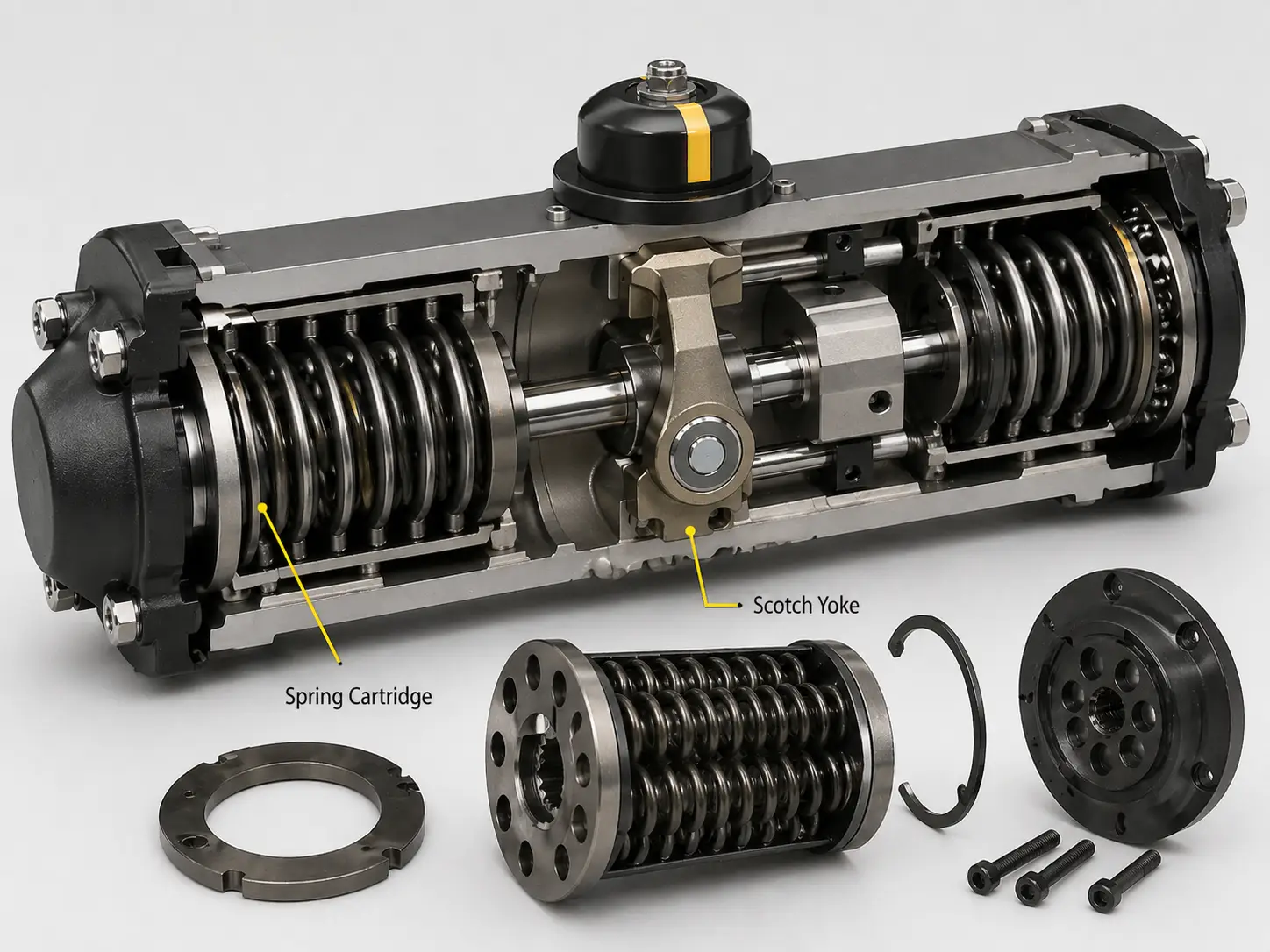
Spring Return (SR) Modules and SIL Requirements
For the most critical ESD valves—the final elements in a Safety Instrumented System (SIS)—safety engineers mandate a single acting scotch yoke pneumatic actuator, universally known as a Spring Return (SR) configuration. In this architecture, air pressure is introduced into the cylinder to stroke the valve while simultaneously compressing a massive, heavy-duty mechanical spring (or a nested array of multiple springs).
The system actively holds this compressed state during normal pipeline operations. If the control system experiences a catastrophic loss of power, a severed air line, or an intentional emergency trip signal, the pneumatic pressure is instantly vented through quick exhaust valves. The immense potential energy stored within the mechanical spring is unleashed, driving the piston backward and rotating the valve to its failsafe position (either Fail-Close to isolate flow, or Fail-Open to relieve pressure to a flare system) without requiring a single joule of external power.
Because these units are the absolute last line of defense, they must undergo rigorous third-party auditing to achieve Safety Integrity Level (SIL) certification per IEC 61508. Actuators deployed in these nodes are typically required to be SIL 2 or SIL 3 capable, guaranteeing extremely low Probability of Failure on Demand (PFD) rates.
Pneumatic vs. Hydraulic Power Sources
Before finalizing the failsafe architecture, plant engineers must deeply evaluate and determine the optimal motive fluid to drive the piston. While the internal kinematics and geometry of the central yoke remain absolutely identical, the physical properties of the power source dictate the actuator’s dynamic response time, dimensional footprint, and maintenance protocols.
Pneumatic systems operate utilizing clean, compressed plant air, typically regulated between 5 to 8 bar (70 to 115 psi). Gases are inherently highly compressible, which gives pneumatic systems exceptionally fast stroke times. This rapid actuation—capable of stroking massive valves in under 3 seconds—makes them the absolute standard for ESD valves that must close almost instantaneously to isolate pipeline ruptures. Furthermore, pneumatic systems are highly cost-effective to install and present zero environmental contamination risk; a blown seal merely vents harmless air into the atmosphere.
Hydraulic systems, conversely, utilize incompressible synthetic fluids operating at extreme pressures, often ranging from 100 to 300 bar (1,450 to 4,350 psi). Because liquids possess a high bulk modulus and do not compress, hydraulic actuators offer perfectly rigid, precise positioning control, eliminating any “spongy” hesitation. The primary engineering advantage here is extreme force density. A hydraulic cylinder can generate massive linear thrust from a surprisingly compact profile. When automating mammoth mainline valves on offshore platforms where structural space is severely restricted, hydraulics are highly preferred, despite requiring complex Hydraulic Power Units (HPUs) and strict fluid cleanliness protocols.
Overcoming Lead Time and QC Bottlenecks in Valve Automation
Specifying the mathematically correct torque curve, yoke geometry, and failsafe architecture is only the theoretical foundation of pipeline automation. In real-world project execution, ensuring timely supply chain delivery and exact metallurgical matching for successful Site Acceptance Tests (SAT) are paramount to project success.
VINCER VALVE is structurally engineered to eliminate these supply chain bottlenecks through a transparent, high-efficiency manufacturing ecosystem. Backed by a 7,200-square-meter facility, four dedicated automated production lines, and over 10 years of specialized fluid control expertise, we provide a mathematically secure pathway from technical sizing to final pipeline installation.
Optimize Your Pipeline Automation with Precision Sizing
We rely on hard engineering data and stringent quality control protocols to ensure every automated valve assembly performs flawlessly under extreme differential pressure.
- Mathematical Torque Overlay Analysis: To prevent catastrophic stem shearing or valve seizure, our engineers plot the exact hydrodynamic and seat interference requirements of your specific valve against our actuator U-curves, verifying that the output perfectly clears your Safety Factors without exceeding the valve’s Maximum Allowable Stem Torque (MAST).
- Accelerated, Predictable Lead Times: Agile production scheduling allows us to deliver standard automated valves in 7 to 10 working days, with complex heavy-duty custom builds completed in just 15 to 30 days.
- 100% Visual and Documentary Verification: Every unit undergoes a rigorous inspection process, including hydrostatic shell testing and dynamic cycle testing. Prior to dispatch, you receive the certificates, high-definition secondary inspection photos and functional test videos. What you approve is exactly what arrives at your site.
Ready to specify your next automated valve package?
Submit your exact operating parameters (Medium, ΔP, Temperature ranges, Space constraints). Our engineering team will provide a preliminary multi-product automation solution within 48 hours, complete with matching 2D/3D CAD dimensional integration.