A practical guide for water treatment engineers covering chemical strategies, material selection, and equipment specification for corrosive environments.
Understanding Corrosion in Water Treatment Systems
Corrosion in water treatment is not a single problem it is an electrochemical system problem. At its core, corrosion is an oxidation-reduction reaction: metal at the anode dissolves into the water, releasing electrons that travel to the cathode, where oxidizing agents like dissolved oxygen accept them. Three components must be present for this to happen: an anode, a cathode, and an electrolyte and in water treatment systems, the water itself is the electrolyte.
The most common corrosion types found in water treatment facilities include uniform corrosion (even metal loss across a surface), pitting corrosion (localized deep penetration that can perforate pipe walls with minimal visible damage elsewhere), galvanic corrosion (triggered when dissimilar metals are in contact in the same water stream), and microbiologically induced corrosion, or MIC, where bacteria colonies create aggressive local chemistry on metal surfaces.
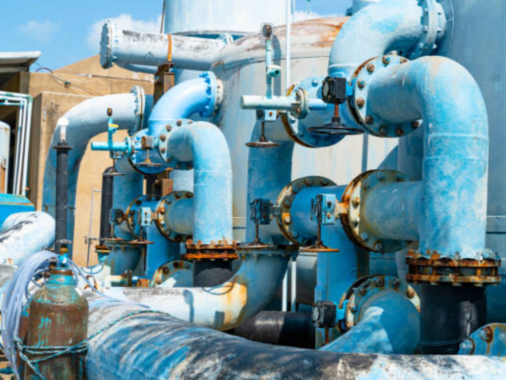
The consequences of ignoring corrosion control fall into three categories. First, health risk: corrosion leaches toxic metals lead, copper, zinc into drinking water. Second, infrastructure damage: pipe perforation and equipment failure cause unplanned shutdowns that ripple through treatment plant operations. Third, operating cost: replacing corroded valves, pumps, and piping runs 3-5 times over a facility’s lifespan when proper material selection could have extended service to 15 or 20 years. Tuberculation the rust-nodule buildup inside old cast-iron pipes is the visible face of this problem, reducing effective pipe diameter and creating breeding grounds for bacteria.
Water Chemistry Parameters That Drive Corrosion
Corrosion is not random. It is driven by measurable water chemistry parameters, and understanding these parameters is the first step toward controlling them. Six factors dominate:
| Water Parameter | Effect on Corrosion | Typical Risk Threshold |
|---|---|---|
| pH | Low pH (acidic water) accelerates metal dissolution by increasing H⁺ ion availability at the cathode | pH < 6.5 significantly increases corrosion rate; target 7.0-8.5 for most systems |
| Alkalinity (as CaCO₃) | Provides buffering capacity; low alkalinity means pH can crash rapidly with acidic inputs | Recommended minimum 30 mg/L for drinking water distribution systems |
| Dissolved Oxygen (DO) | Drives the cathodic half-reaction; higher DO = faster corrosion unless a protective oxide layer has already formed | Concentration above 2-4 mg/L in untreated water accelerates uniform corrosion |
| Total Dissolved Solids (TDS) | Increases water conductivity, enhancing the electrochemical corrosion cell | TDS > 500 mg/L significantly increases conductivity; seawater is ~35,000 mg/L |
| Chloride (Cl⁻) | Most aggressive ion for pitting corrosion; breaks down passive oxide films on stainless steel | > 250 mg/L raises pitting risk for 304SS; seawater chloride ~19,000 mg/L demands duplex or non-metallic materials |
| Temperature | Accelerates reaction kinetics; also reduces dissolved gas solubility (complex net effect) | Rule of thumb: corrosion rate doubles for every 10°C increase |
These parameters do not act in isolation. Low pH combined with high chloride is the most dangerous pairing in any water treatment system the acidic environment strips away protective oxide layers, and chloride ions attack the exposed metal surface before a new passive film can form. The Langelier Saturation Index (LSI), which predicts whether water will be corrosive or scale-forming based on pH, alkalinity, calcium hardness, temperature, and TDS, remains the most widely used screening tool. An LSI below -0.5 signals corrosive water; above +0.5 signals scaling tendency.
A useful mental model: seawater versus deionized water. Most people assume pure water is safe. In reality, deionized water is aggressively corrosive because it has zero buffering capacity it will pull ions from any metal it touches to restore equilibrium. Seawater, despite its intimidating reputation, is manageable if you select the right materials. The difference is knowing the chemistry.
Chemical Treatment Methods for Corrosion Control
Chemical corrosion control follows one central logic: create a barrier between the metal surface and the water. This barrier is either a chemical film inhibitors adsorbing onto the pipe wall or a thermodynamic one, where you adjust water chemistry so the water itself deposits a thin, protective calcium carbonate scale. The two strategies work together, not against each other.
Corrosion Inhibitors: Phosphate, Silicate, and Emerging Alternatives
The most widely deployed corrosion inhibitors in water treatment fall into three families:
| Inhibitor Type | Mechanism | Best Application | Key Limitation |
|---|---|---|---|
| Orthophosphate (PO₄³⁻) | Forms a protective iron-phosphate film on metal surfaces by reacting with corrosion products at the anode | Drinking water distribution lead and copper corrosion control per EPA Lead and Copper Rule | Requires continuous dosing at 0.5-3.0 mg/L as PO₄; underdosing can accelerate pitting |
| Polyphosphate | Sequesters dissolved metals and forms a glassy film; also controls scale | Blended with orthophosphate for mixed corrosion-scale control programs | Reversion risk: at elevated temperatures, polyphosphates hydrolyze back to orthophosphate, causing unintended calcium phosphate scaling |
| Sodium Silicate | Forms a thin silica gel film on metal surfaces over 4-8 weeks of continuous application | Low-alkalinity soft waters where phosphate may be restricted | Film formation is slow; does not protect against existing corrosion damage |
Orthophosphate is the workhorse of drinking water corrosion control in the United States, recommended by the EPA’s Optimal Corrosion Control Treatment Evaluation Technical Recommendations for lead and copper compliance (EPA, 2023). The mechanism is straightforward: phosphate reacts with iron corrosion products at the anode to form a dense, adherent film that blocks further metal dissolution.
A newer direction in inhibitor chemistry is the shift toward low-phosphorus and bio-based alternatives. Phosphorus discharge from water treatment plants contributes to eutrophication in receiving waters a regulatory pressure that is only increasing. Products like Solugen’s AcquaCore represent a bio-based, non-toxic alternative, though their long-term performance data set is still smaller than phosphate’s decades of field history.
pH Adjustment and Alkalinity Control for System Stability
Raising pH is the cheapest corrosion control measure available and the one most frequently underinvested in. The target pH range depends on the system: drinking water distribution aims for 7.0-8.5, while industrial cooling water systems often run higher, at 7.5-9.0, to compensate for elevated temperatures.
The three common alkalinity adjustment chemicals each have distinct trade-offs:
| Chemical | Formula | Best Suited For | Considerations |
|---|---|---|---|
| Lime (Calcium Hydroxide) | Ca(OH)₂ | Large municipal plants with high throughput | Adds both calcium and alkalinity; requires slurry handling equipment; most cost-effective at scale |
| Caustic Soda (Sodium Hydroxide) | NaOH | Medium to large systems; liquid feed simplifies automation | Raises pH without adding calcium; does not increase calcium carbonate precipitation potential (CCPP) |
| Soda Ash (Sodium Carbonate) | Na₂CO₃ | Small systems; easy to handle as dry powder | Adds alkalinity but no calcium; higher cost per unit of alkalinity than lime |
But adjusting pH without addressing alkalinity is a half-measure. Low-alkalinity water even at a neutral pH of 7.0 has almost no buffering capacity. A small acid input (acid rain, chemical feed upset) can send the pH crashing, and the pipe wall’s protective scale dissolves in minutes. The minimum recommended alkalinity for stable drinking water distribution is 30 mg/L as CaCO₃. The LSI target range of -0.5 to +0.5 keeps water slightly scale-forming without risking heavy scaling.
Think of it like swimming pool chemistry: pool operators know they must monitor both pH and total alkalinity, because without alkalinity, pH bounces wildly with every chemical addition. Corrosion control in water treatment follows the same principle alkalinity is the shock absorber.
Equipment-Level Defense: Selecting Corrosion-Resistant Valves and Materials
Chemical treatment handles the water side of the equation. But there is another half of corrosion control that the standard SERP coverage almost entirely ignores: selecting equipment materials that fundamentally resist the corrosive environment. The best chemical inhibitor program cannot save a 304 stainless steel valve installed in seawater service. Equipment material selection is not a backup plan it is the first line of defense.
Before diving into material grades, use this self-assessment framework: What is your fluid? (Clean water? Chlorinated? Acidic? Seawater?) What are your temperature and pressure ranges? And critically are you calculating cost based on purchase price or 10-year total cost of ownership? Answering these three questions before any material specification saves more money than any post-installation corrosion repair program.
Material Grades: 304SS vs 316SS vs Duplex vs PTFE-Lined vs Plastics
The single most common mistake in water treatment equipment specification is ordering “stainless steel” without specifying the grade. The difference between 304 and 316 is roughly 2% molybdenum. In the presence of chloride ions, that 2% is the difference between a 15-year service life and pitting perforation within 6 months.
| Material Grade | Chloride Resistance (Approx. Threshold) | Max Continuous Temp | Best Water Treatment Application | Relative Cost |
|---|---|---|---|---|
| 304 Stainless Steel (CF8) | 100-200 ppm Cl⁻ (pitting risk escalates above this) | ~400°C (material limit, not service) | Indoor freshwater systems, low-chloride process water | Baseline (1.0×) |
| 316 Stainless Steel (CF8M) | 500-1000 ppm Cl⁻ (molybdenum provides pitting resistance) | ~400°C | Coastal installations, chlorinated water, moderate chemical exposure | ~1.3× |
| Super Duplex 2507 (CE3MN) | >10,000 ppm Cl⁻ (PREN ≥40; resists chloride stress corrosion cracking) | ~300°C | Seawater desalination, RO brine, offshore platforms | ~3-4× |
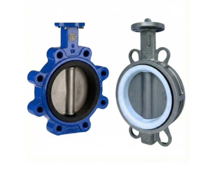
| PTFE-Lined Carbon Steel | Near-universal chemical resistance up to ~180°C | ~180°C (lining limit) | Concentrated acids/alkalis, chemical dosing lines | ~1.5-2× |
| UPVC / CPVC | Inert to most water treatment chemicals; no metallic corrosion | ~60°C (UPVC) / ~95°C (CPVC) | Low-pressure corrosive lines, chemical storage, seawater intake | 0.3-0.5× |
The critical decision rule: if your water has chloride above 250 ppm, eliminate 304SS from consideration go directly to 316 as the minimum. For seawater applications (19,000 ppm chloride), Super Duplex is the baseline metallic option; plastic valves (UPVC/CPVC) or PTFE-lined valves are often the more cost-effective choice for low-to-moderate pressure seawater services. For concentrated acid or alkali streams common in chemical cleaning and pH adjustment systems PTFE-lined valves are the only reliable metallic-bodied solution, handling concentrations of 90% or above.
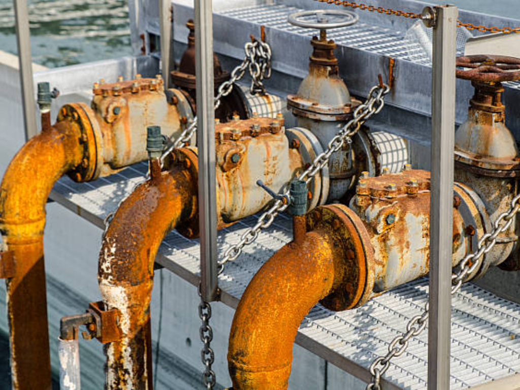
Watch out for the assumption that “stainless means no corrosion.” Stainless steel resists corrosion by forming a passive chromium oxide film. Chloride ions penetrate that film at discrete points. Once a pit initiates, the local chemistry inside the pit becomes far more aggressive than the bulk water a self-accelerating failure mode that can perforate a valve body with almost no visible damage elsewhere on the surface. A 304 valve in coastal service can fail in under a year while looking pristine from the outside.
Coastal water treatment plant 304SS <1 year
Same material. One variable: chloride.
Valve Types for Different Water Treatment Applications
Different process zones within a water treatment plant face fundamentally different corrosion challenges. Matching valve type and material to each zone prevents the most common cause of premature valve failure: using the right valve in the wrong place.
| Process Zone | Primary Corrosion Challenge | Recommended Valve Type | Material Specification |
|---|---|---|---|
| Chemical Dosing (coagulant, inhibitor, acid/alkali feed) | Concentrated chemicals; precise flow control required | Globe control valve with 4-20 mA positioner | PTFE-lined body (acids/alkalis) or 316SS (standard chemicals); characterized trim for linear or equal-percentage flow |
| Seawater Intake & RO High-Pressure Feed | High chloride (19,000+ ppm); high pressure (60-80 bar for SWRO) | Butterfly valve (DN200+) for main isolation; ball valve (DN15-100) for sample/instrument lines | Super Duplex 2507 body and disc; EPDM or Viton seat |
| Sludge & Solids Handling | Abrasive solids + corrosive filtrate water; thick, high-solids media | Knife gate valve (full-bore, bidirectional sealing) | 316SS body with PTFE or EPDM seat; hard-faced gate for abrasive service |
| Drinking Water Distribution | NSF/ANSI 61 & 372 compliance required; moderate chlorine residual | Gate valve (resilient-seated, OS&Y) or butterfly valve for large diameters | Ductile iron body with fusion-bonded epoxy coating (≥200 µm DFT per AWWA C550); 316SS stem and fasteners |
| CIP & Acid Wash Systems | Hot concentrated acids/alkalis cycled during clean-in-place | Ball valve (full-port, cavity-filled) | PTFE-lined body with PTFE seats and seals |
For chemical dosing systems, the non-negotiable requirement is precise, repeatable flow control. Globe control valves with characterized trim linear for steady-state dosing, equal-percentage for wide turndown paired with a 4-20 mA positioner, give operators the confidence that corrosion inhibitor dosage stays within the narrow window where protection works. Too little, and the protective film breaks down; too much, and chemical cost balloons without additional benefit.
For drinking water distribution, the regulatory overlay adds a second dimension beyond corrosion resistance: every valve in contact with potable water must comply with NSF/ANSI 61 (health effects) and NSF/ANSI 372 (low lead, ≤0.25% weighted average). Ductile iron gate valves with fusion-bonded epoxy coating to AWWA C515, using 316 stainless steel stem and fasteners, have become the standard specification for water utilities across North America.
Protective Coatings and Linings for Extended Service Life
Even the right base material benefits from an additional defense layer. Coatings protect the external surface from atmospheric corrosion; linings protect the internal wetted surface from the process fluid. Both are essential, and both have failure modes that are predictable if you know what to look for.
Fusion-bonded epoxy (FBE) is the default coating for water treatment valves and fittings. Applied at a minimum dry film thickness of 200 µm per AWWA C550, FBE provides effective corrosion protection in pH 4-9 environments which covers the vast majority of water treatment services. The coating is factory-applied and heat-cured, creating a bond that resists both mechanical handling damage and cathodic disbondment. For buried valves, a minimum 200 µm FBE coating on both internal and external surfaces, supplemented by cathodic protection where soil conditions warrant, is standard industry practice per ISO 12944-2 Corrosivity Category C4 (high-corrosivity industrial/coastal environments).
PTFE and PFA linings serve a different purpose: they protect the valve body from aggressive chemicals that would attack any metallic material. In concentrated acid service, a PTFE-lined ball or butterfly valve can handle media that would destroy a Super Duplex valve within hours. But a lining is only as good as its integrity. A single pinhole in a PTFE lining lets the corrosive medium reach the carbon steel shell, creating a concentrated corrosion cell far more aggressive than if the valve had no lining at all. The trapped corrosion products can eventually bulge or crack the lining from behind. For critical service, specify lined valves with a spark test (holiday detection) at the factory and schedule periodic re-inspection during service.
15-20% Maintenance, Downtime & Replacement
80%+
For operators evaluating the economics: the incremental cost of specifying FBE-coated ductile iron valves instead of uncoated cast iron is roughly 15-20% on the purchase order. Against that, a coated valve in water treatment service typically delivers 15-20 years of service life versus 3-5 years for uncoated material in the same environment. The math favors the coating every time.
Valve manufacturers who specialize in corrosion-resistant designs such as VINCER, whose PTFE-lined ball and butterfly valve series handles acid and alkali concentrations of 90% and above offer material and coating combinations purpose-built for water treatment applications. Consulting with an application engineer during the specification phase helps match the right material-lining combination to each process zone, avoiding the most expensive mistake in valve procurement: buying the same specification for every position regardless of the corrosion environment each valve actually faces.
Building an Integrated Corrosion Management Strategy
Chemical treatment and equipment material selection are not alternatives they are two halves of one strategy. Chemical inhibitors and pH control manage the water’s corrosive potential; material selection, valve type matching, and protective coatings manage the equipment’s corrosion resistance. A weakness in either half undermines the entire system.
Different process zones within the same water treatment plant face different corrosion profiles, and the strategy should reflect that. The chemical dosing area needs PTFE-lined valves and precise metering pumps. The sludge handling line needs abrasion-resistant knife gate valves. The treated water distribution network needs NSF-compliant coated gate valves. A one-size-fits-all valve specification is a procurement shortcut that becomes an operations headache within the first maintenance cycle.
The financial case is straightforward and backed by data. Industry analysis consistently shows that the purchase price of a valve represents only 15-20% of its total lifecycle cost. The remaining 80% or more comes from maintenance labor, unplanned downtime, replacement procurement, and in the worst case environmental or regulatory penalties from a corrosion-related failure. Spending 20% more upfront on correctly specified corrosion-resistant equipment routinely avoids 80% of the lifetime cost burden. It is one of the highest-return capital decisions a water treatment operator can make.
The right starting point is a process-zone-by-process-zone audit of corrosion risks, current material specifications, and failure history. For each zone, ask: what is the fluid chemistry, what is the most common failure mode here, and is the current valve material specification adequate for the actual not the design-basis operating conditions? The answers to those three questions will surface the highest-priority upgrades faster than any generic checklist.
References
- U.S. Environmental Protection Agency. “Drinking Water Standards and Regulations.” https://www.epa.gov/dwstandardsregulations
- American Water Works Association. “AWWA C550 Protective Interior Coatings for Valves and Hydrants.” https://www.awwa.org
- International Organization for Standardization. “ISO 12944-2:2017 Paints and varnishes Corrosion protection of steel structures by protective paint systems.” https://www.iso.org/standard/67092.html
- VINCER Valve. “Electric Actuated Valves.” https://www.vincervalve.com/electric-actuated-valve/
- VINCER Valve. “Pneumatic Actuated Valves.” https://www.vincervalve.com/pneumatic-actuated-valve/
- VINCER Valve. Homepage. https://www.vincervalve.com/