An exhaustive engineering guide to maximizing heat transfer efficiency, navigating chemical vs. non-chemical alternatives, and deploying intelligent automation to protect your multi-million dollar equipment across HVAC, data centers, chemical processing, power generation, and water treatment facilities.
What Is a Cooling Tower Water Treatment System?
In the expansive realm of industrial manufacturing, petrochemical processing, large-scale power generation, hyper-scale data centers, municipal water treatment facilities, and massive commercial HVAC installations, the cooling tower is universally recognized as the “industrial lung” of the entire facility. These monumental heat rejection devices are responsible for dissipating millions of British Thermal Units (BTUs) of waste heat into the atmosphere every single hour.
However, without a meticulously engineered, continuously operating cooling tower water treatment system, this vital organ quickly deteriorates, bringing the entire thermal network to a catastrophic, grinding halt. At its core, an industrial cooling tower water treatment system is not merely a collection of pipes and chemical drums. It is a highly complex, fully automated ecosystem comprising advanced side-stream filtration units, precision chemical dosing stations, real-time analytical monitoring sensors, and highly responsive automated blowdown valves. Its ultimate mission extends far beyond the oversimplified concept of merely “cleaning water.” Its true operational purpose is to protect the massive capital expenditure (CAPEX) of your centrifugal chillers, titanium heat exchangers, and critical process equipment by tightly controlling the fluid chemistry at the microscopic heat transfer interface.
To understand why this is a non-negotiable engineering requirement rather than an optional maintenance line item, one must thoroughly grasp the thermodynamics of the “Concentration Effect” and the rigorous mass balance equations of an open recirculating cooling loop. As a cooling tower operates, it rejects building or process heat by evaporating water into the atmosphere. The thermodynamics of latent heat of vaporization dictate that for every 1,000 BTUs of heat rejected, approximately one pound of water must be physically evaporated.
When this pure water vapor leaves the tower and enters the atmosphere, it leaves behind 100% of the dissolved minerals, silica, heavy salts, and scrubbed airborne debris in the remaining basin water. Without dynamic mechanical and chemical intervention, this circulating fluid rapidly transforms from benign tap water into a highly concentrated, chemically aggressive, corrosive, and heavily scaling “brine.” A comprehensive cooling water treatment protocol acts exactly like a continuous dialysis machine for your HVAC infrastructure. It works relentlessly 24/7, filtering out suspended solids, chemically balancing the pH and alkalinity, and continuously purging this toxic fluid to maintain a strict state of thermodynamic equilibrium. Failure to implement this exacts a severe toll on facility operations, triggering the three primary modes of catastrophic mechanical failure: mineral scaling, electrochemical corrosion, and severe microbiological fouling.
The Invisible Threats: Deep Dive into Scaling, Corrosion, and Biological Fouling
Before diving into the mechanical anatomy and specific hardware of the water treatment equipment itself, engineers and facility operators must clearly define the three distinct physical and chemical inevitabilities that dictate cooling tower water treatment processes. Ignoring these persistent threats transforms a highly efficient thermodynamic loop into an energy-devouring liability. The complex interplay between fluid dynamics, atmospheric contamination, and aqueous chemistry creates a volatile environment where failure to proactively manage one single variable inevitably triggers a cascading failure across the entire mechanical system.
Mineral Scaling: The Ultimate Thermal Insulator
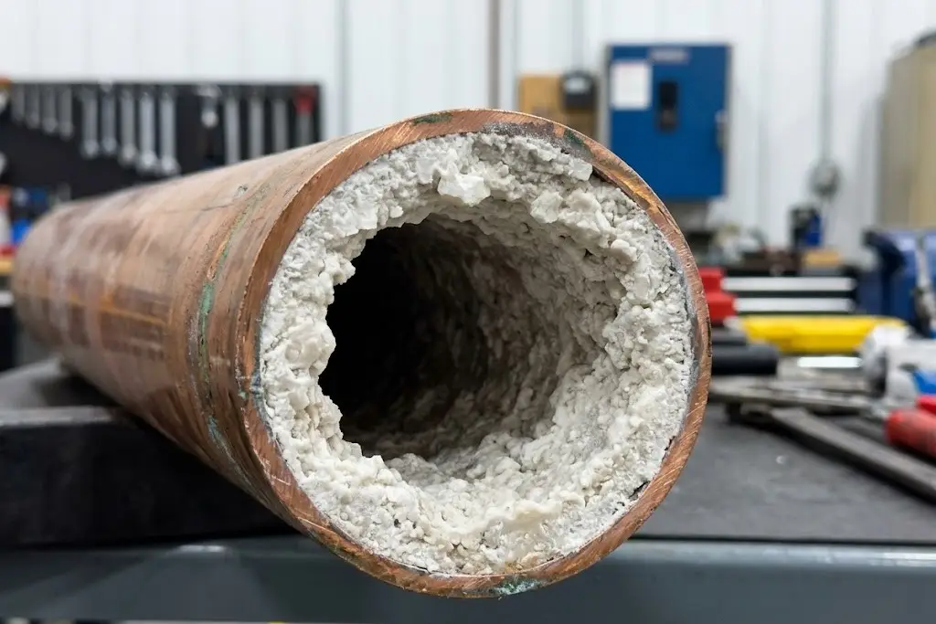
Scaling is a precipitation process that occurs when the concentration of dissolved minerals – primarily calcium carbonate (CaCO3), calcium sulfate (CaSO4), magnesium silicate, and silica (SiO2) – exceeds their natural solubility limits and precipitates out of the aqueous matrix, crystallizing directly onto hot heat exchange surfaces. Unlike most soluble substances which dissolve easier in hot water, calcium carbonate exhibits a unique physical property known as inverse solubility. This means it actually becomes less soluble as the water temperature increases. This critical thermodynamic quirk is precisely why the hottest parts of your system, specifically the internal walls of your chiller’s condenser tubes, are always the first to suffer from severe mineral scaling.
Silica scale is particularly dreaded among industrial water treatment engineers. While basic calcium carbonate scale can often be dissolved and flushed out with routine mild acid cleaning (such as sulfamic or citric acid flushes), silica scale forms a dense, hard, glass-like coating that is chemically inert to most standard cleaning acids. Once silica bakes onto a heat exchanger, it often requires highly hazardous hydrofluoric acid treatments or destructive mechanical drilling to remove, severely threatening the integrity of the copper tubes.
To mathematically predict this scaling tendency, the industry relies on calculated thermodynamic indices, predominantly the Langelier Saturation Index (LSI) and the Ryznar Stability Index (RSI). The LSI is a complex equation factoring in the water’s pH, temperature, total dissolved solids (TDS), total alkalinity, and calcium hardness. An LSI value perfectly at 0.0 indicates water that is perfectly balanced — neither scaling nor corrosive. A negative LSI indicates aggressive, corrosive water. A positive LSI indicates a strong thermodynamic drive for calcium carbonate to precipitate and form scale.
In modern high-efficiency engineering practices, facility managers do not aim for a 0.0 LSI. Instead, maintaining an LSI slightly above zero (typically ranging from +0.5 to +2.0) is intentionally targeted. This slightly scaling environment provides a microscopic, protective passivating layer of calcium carbonate over the raw metal, shielding it from corrosion. However, this high-stress strategy must be rigorously executed in conjunction with advanced polymer dispersants. These specialized polyacrylate and phosphonate dispersants chemically modify the crystal lattice growth of the scale. Through steric hindrance and charge repulsion, they prevent the microscopic calcium crystals from agglomerating and adhering to the condenser tube walls, keeping them safely suspended in the bulk fluid until they can be removed via the automated blowdown valve.
The financial impact of failing to control mineral scaling is brutal and immediate. Mineral scale is an exceptional thermal insulator, boasting a thermal conductivity that is a fraction of copper or steel. A microscopic layer of scale, merely 1 millimeter thick, acts as a thermal blanket, forcing the chiller’s compressor to work exponentially harder to reject the same thermal load. This significantly drives up the condenser “approach temperature” and permanently destroys the chiller’s Coefficient of Performance (COP), leading to devastating electrical utility bills.
Corrosion: The Relentless Asset Destroyer
While scaling drastically reduces thermal efficiency and inflates OPEX, uncontrolled corrosion represents a much darker threat: it permanently destroys the physical integrity of the equipment (CAPEX). Cooling water, especially when highly oxygenated from the violent cascading action inside the cooling tower fill media, acts as an extremely aggressive electrolyte. This highly conductive fluid creates the perfect storm for multiple forms of metal degradation, including galvanic corrosion, localized pitting, crevice corrosion, and generalized uniform thinning.
Corrosion in industrial cooling systems is, fundamentally, a complex electrochemical process. It involves the transfer of electrons from one metal surface to another, facilitated by the conductive water. Anodic and cathodic half-cell reactions systematically eat away at your expensive piping walls. At the anodic site, pure metal (like iron or copper) oxidizes and dissolves into the water as positive ions, leaving behind electrons. These electrons travel through the metal to the cathodic site, where they typically reduce dissolved oxygen into hydroxide ions. The constant flow of this microscopic electrical current literally dissolves your equipment from the inside out.
Furthermore, systems constructed with multiple metals face the severe threat of galvanic corrosion. When dissimilar metals, such as copper heat exchanger tubes and carbon steel distribution pipework, are electrically connected in the presence of the cooling water electrolyte, the less noble metal (the carbon steel) becomes the anode and corrodes at a violently accelerated rate to protect the more noble metal (the copper).
Cooling towers constructed with galvanized steel face their own unique electrochemical threat known as “White Rust.” This is a rapid, catastrophic depletion of the protective zinc coating, typically caused by operating the newly installed tower at a pH consistently above 8.2 or with insufficient alkalinity during the critical initial passivation phase. If the zinc layer is stripped, the underlying mild steel is exposed to the oxygen-rich water, leading to rapid system failure.
If these complex electrochemical reactions are left unchecked by the precise application of anodic and cathodic corrosion inhibitors (such as molybdates, orthophosphates, nitrites, or specialized zinc compounds), localized pitting corrosion can penetrate a standard copper condenser tube wall in a matter of months. Pitting is particularly dangerous because it focuses the entire corrosive attack on a microscopic pinhole area, rapidly boring through the metal. This eventually leads to catastrophic cross-contamination between the cooling water and the closed-loop refrigerant, massive refrigerant loss into the atmosphere, unplanned emergency downtime, and premature equipment replacement running into hundreds of thousands, if not millions, of dollars.
Biological Fouling: The Insidious and Silent Amplifier
Cooling towers represent the ultimate, perfect environment for microbiological proliferation. They are warm, constantly wet, highly oxygenated, and heavily laden with organic nutrients scrubbed directly from the ambient air (such as dust, pollen, bird droppings, and industrial exhaust). In this ideal industrial bioreactor, airborne bacteria, algae, protozoa, and fungi thrive exponentially, rapidly forming dense, slimy biological communities known as biofilms on all wetted system surfaces.
Biofilm is arguably the most insidious and difficult-to-treat threat in any cooling water system. The living bacteria secrete a sticky, glue-like matrix called Extracellular Polymeric Substances (EPS). This EPS slime layer firmly anchors the bacterial colony to the pipe walls and acts as an impenetrable shield against standard chemical treatments. The thermal insulating properties of this biofilm are catastrophic; because biofilm is composed of mostly stagnant water trapped within the EPS matrix, its thermal resistance is up to four times worse than an equivalent thickness of hard calcium carbonate scale. A condenser fouled with biofilm will see its efficiency plummet almost overnight.
Furthermore, biofilm creates a highly dangerous environment for localized corrosion. As the biofilm thickens, oxygen cannot penetrate to the bottom layers touching the metal pipe. This creates an anaerobic (oxygen-free) micro-environment where specialized bacteria, specifically Sulfate-Reducing Bacteria (SRB), begin to thrive. SRBs consume sulfates present in the water and excrete hydrogen sulfide gas as a metabolic byproduct. This highly toxic and acidic gas reacts with the iron in the pipes, causing extremely aggressive and rapid Microbiologically Influenced Corrosion (MIC). These localized acidic micro-environments can bore massive pits through standard carbon steel, copper, and even highly resistant 316L stainless steel effortlessly.
Therefore, comprehensive cooling tower water treatment services do not treat biological control as a secondary objective. Aggressive, multi-stage microbiological control is prioritized not just for mitigating the severe public health risks of airborne pathogens, but as the foundational pillar of long-term asset preservation and energy efficiency.
Anatomy of a Cooling Tower Water Treatment System
Transforming raw municipal, well, or surface water into a stable heat transfer medium requires a highly sequential, heavily automated mechanical approach. The fundamental governing mass balance equation of any cooling loop is: Makeup = Evaporation + Blowdown + Drift + System Leaks. Let’s deconstruct the system into its primary functional blocks, moving from the point of fluid entry to the point of automated discharge.
Makeup Water and Pre-Treatment Stages
Every single gallon of water evaporated by the cooling tower must be instantly replaced by “makeup water.” The precise chemical profile of this incoming water – specifically its calcium/magnesium hardness, silica concentration, total alkalinity, heavy metals, and initial pH levels – fundamentally dictates the entire downstream treatment strategy and chemical procurement budget. Pre-treatment acts as the crucial frontline defense. Ignoring the holistic makeup water profile and buying “off-the-shelf” chemical blends is the most common root cause of catastrophic system failure.
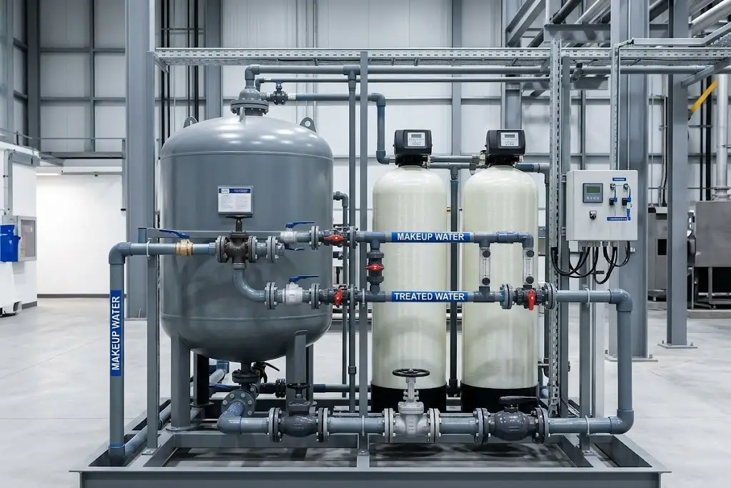
In regions plagued with exceptionally hard water (high calcium/magnesium content), industrial water softeners utilizing sodium-based ion-exchange resins are frequently deployed. These massive fiberglass tanks physically strip the calcium from the makeup water before it ever enters the cooling loop. Alternatively, for extremely challenging water sources or zero-liquid-discharge goals, Reverse Osmosis (RO) systems might be employed. By proactively removing these “rock-forming” minerals at the gate, the reliance on expensive downstream chemical scale inhibitors is drastically reduced. More importantly, this enables the cooling tower to safely run at significantly higher cycles of concentration without fear of sudden mineral precipitation.
The Chemical Dosing Station and Automation Panel
The true operational brain of modern cooling tower solutions lies in the PLC-based (Programmable Logic Controller) automation panel. Relying on manual chemical dumping via buckets is a hazardous relic of the past that guarantees wild swings in water chemistry, wasted chemical budgets, and highly dangerous bio-blooms. Today’s advanced systems utilize sophisticated inline analytical probes to monitor pH, conductivity, and Oxidation-Reduction Potential (ORP) continuously, 24/7/365.
ORP sensors function as the system’s active radar, dynamically measuring the water’s actual sanitizing strength in millivolts (mV), rather than just blindly calculating raw chemical volume injected. These automation panels control precision triple-pump chemical feed skids utilizing advanced PID (Proportional-Integral-Derivative) control logic. This prevents dangerous overshooting or undershooting of chemical setpoints.
Because microbiological organisms are highly adaptive, a robust cooling tower chemical protocol absolutely requires “alternating shock dosing.” This involves using the automation panel to alternate between a primary fast-acting oxidizing biocide (like sodium hypochlorite, bromine, or chlorine dioxide) which literally oxidizes and burns through cell walls, and a secondary non-oxidizing biocide (like isothiazolinone, glutaraldehyde, or DBNPA) which disrupts the bacteria’s internal metabolism and reproductive capabilities. This dual-pronged, staggered attack prevents the bacterial colonies from developing genetic immunity and forming resistant super-strains.
Automated Blowdown Valves: The Execution Bottleneck
As pure water evaporates, the remaining dissolved minerals concentrate exponentially. To prevent supersaturation and massive scaling events, a precisely calculated portion of this highly concentrated water must be continuously or periodically discharged to the drain — a critical process known as “blowdown” or “bleed-off.” The automation panel triggers this sequence based on strict microSiemens (µS/cm) conductivity thresholds, signaling a valve to open.
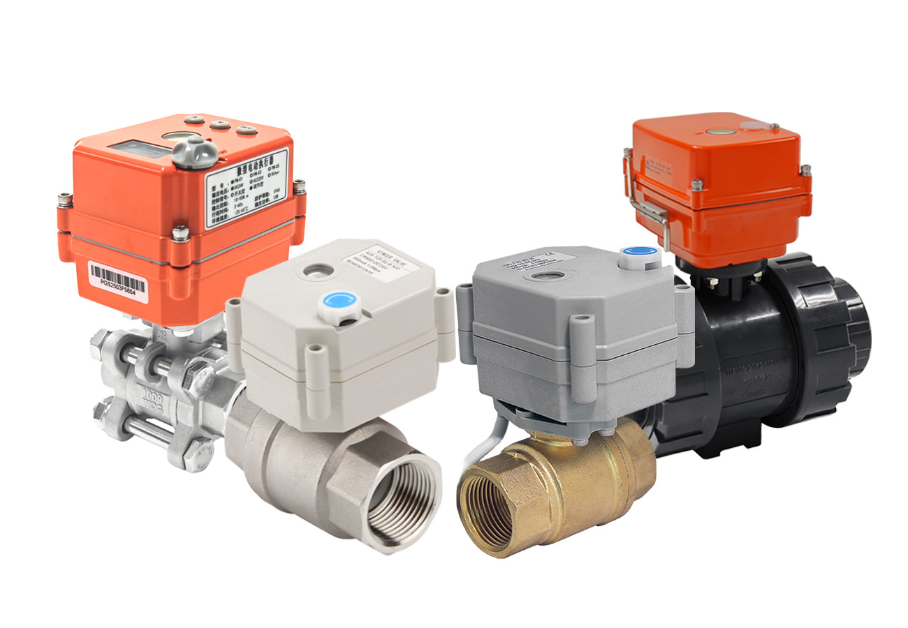
However, the most sophisticated chemical algorithm and high-end PLC controller is completely useless if the mechanical execution fails at the pipe level. This is where the critical importance of the automated control valve comes into play. If a low-quality, generic brass solenoid valve or a slow-acting manual gate valve is used, it will inevitably stick partially open due to particulate buildup, scale, or corrosion from the oxidizers. To handle high concentrations of aggressive oxidants, corrosive chlorides, and heavy Total Suspended Solids (TSS) typical in blowdown scenarios, industrial engineering best practices dictate the exclusive use of robust pneumatic actuated V-port ball valves or high-performance Teflon-lined butterfly valves. A valve that does not close with absolute, verifiable zero-leakage precision results in a continuous chemical bleed. This effectively flushes your incredibly expensive water treatment chemicals straight down the drain, permanently destroying your calculated ROI.
Mastering Side-Stream Filtration for Maximum Efficiency
Many facility managers mistakenly view side-stream filtration as an optional luxury, often the first item to be cut during initial project value engineering (VE). In reality, it is a vital, non-negotiable energy-saving and chemical-reduction mechanism for any cooling loop over 500 tons. Cooling towers, by their very design, act as massive atmospheric air scrubbers. They pull in hundreds of pounds of airborne dust, pollen, insects, and industrial exhaust annually. This Total Suspended Solids (TSS) load inevitably settles in the low-velocity areas of the tower basin, creating a thick, nutrient-rich sludge.
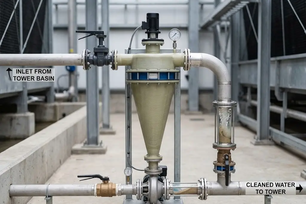
A properly sized side-stream filter (such as a centrifugal separator or a high-efficiency sand media filter) continuously pulls 5% to 10% of the total circulating water, physically removes the suspended particles down to 5-10 microns, and returns the polished water to the loop. Why does this matter for OPEX? Suspended solids consume massive amounts of your oxidizing biocides. If your water is dirty, the expensive chemicals attack the inert dirt instead of the live bacteria. By physically removing the dirt, you completely remove the “safe harbor” where bacteria hide, drastically improving biocide efficacy, protecting delicate valve seals and pump impellers from severe abrasion, and ultimately slashing your annual chemical procurement costs by up to 30%.
Chemical vs. Non-Chemical Treatment: A Pragmatic Engineering Comparison
The ongoing engineering debate between traditional chemical inhibitors and emerging physical (non-chemical) treatment methods requires a brutally objective evaluation. Engineers must perfectly match the technology to the site’s specific environmental constraints, municipal wastewater discharge limits, available CAPEX, and corporate sustainability goals.
| Technology Type | Initial CAPEX | OPEX & Maintenance | Environmental Impact | Critical Limitations & Ideal Applications |
|---|---|---|---|---|
| Traditional Chemical (Polymer Dispersants, Biocides, Inhibitors) |
Low | High (Ongoing chemical purchases, delivery logistics, manual handling risks) | High (Toxic blowdown, strict municipal limits on heavy metals and phosphorus) | Limitation: Heavy regulatory scrutiny and liability. Ideal: Standard commercial buildings, sites with extremely low initial capital budgets. |
| Electrolytic Systems (Electrocoagulation / Precipitation) |
High | Medium (Periodic electrode cleaning/replacement, sustained electrical power consumption) | Very Low (Zero added synthetic toxins) | Limitation: High initial cost, requires relatively steady base conductivity to function. Ideal: Hyper-scale data centers, LEED Platinum green buildings aiming for safe municipal discharge. |
| UV / Ozone Systems (Physical Eradication) |
Medium-High | Medium (Annual bulb replacement, sustained electrical power consumption) | Low (Zero chemical residue or blowdown toxicity) | Limitation: No residual protection in the piping network. Biofilm can easily form in dead legs. Ideal: Must be paired with a secondary chemical biocide for comprehensive protection. |
The Fatal Flaw of Pure UV/Ozone Systems
While Ultraviolet (UV) light and Ozone generation are exceptional, hospital-grade technologies for eradicating bacteria at the exact point of contact (within the enclosed reactor chamber), they share a fatal engineering flaw when used as standalone solutions in sprawling industrial systems: they provide absolutely no residual protection throughout the vast miles of piping in a facility. Water that is perfectly sterile leaving the UV chamber can easily become critically re-contaminated when it reaches a low-flow “dead leg” or a remote heat exchanger where biofilm has already established a foothold. To safely deploy UV or Ozone, engineers must still supplement the physical system with a low-level chemical residual (like a continuous mild chlorine feed) to protect the distal ends of the cooling loop.
Emerging Electrolytic Alternatives
Advanced electrolytic systems offer a holistic physical approach to both scaling and biological control. By passing the cooling water through a direct current (DC) reactor chamber, these systems force calcium and magnesium to precipitate harmlessly onto a cathode (by creating a localized high-pH environment at the metal surface), while simultaneously generating reactive oxygen species (ROS) and free chlorine from naturally occurring chlorides at the anode to kill bacteria. Because no highly toxic synthetic chemicals are added, the blowdown water is generally exempt from severe toxic discharge penalties.
(Crucial Engineering Note: Despite being heavily marketed as “chemical-free,” electrolytic blowdown water is still highly concentrated with natural dissolved salts, chlorides, and high alkalinity. It must be safely directed to the municipal sanitary sewer. Without first passing through an extensive RO desalination plant, electrolytic blowdown water must absolutely never be used for landscape irrigation, as the high salinity will rapidly destroy soil mechanics and kill all plant life.)
Legionella Compliance and the ASHRAE 188 Standard
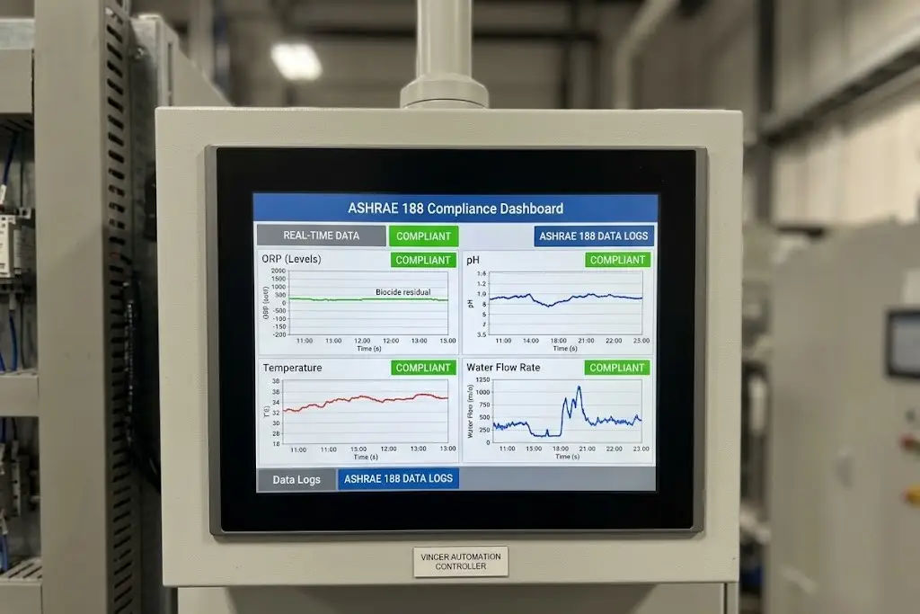
When a cooling tower operates, the massive induced-draft fans release a fine mist of water droplets (known as drift) into the atmosphere. If the basin water is contaminated with the bacteria Legionella pneumophila, this drift becomes a highly effective, weaponized delivery system for Legionnaires’ disease (a severe, often fatal form of pneumonia), capable of infecting vulnerable individuals miles away depending on prevailing wind patterns and humidity. The publication of the ASHRAE Standard 188 (Legionellosis: Risk Management for Building Water Systems) established the definitive, legally binding baseline for care regarding commercial and industrial building water systems.
Compliance with ASHRAE 188 is no longer a best-practice suggestion; it is a strict legal liability issue that demands a comprehensive, living Water Management Plan (WMP) customized by an expert team. This WMP must include a detailed process flow diagram, a rigorous risk hazard analysis, automated continuous biocide dosing capabilities, and rigorous, unalterable digital data logging of water parameters. In the event of a municipal outbreak traced back to a facility, building owners without automated digital data logs proving consistent ORP levels and biocide residuals face catastrophic legal exposure, multimillion-dollar negligence lawsuits, and severe, irreversible reputational damage. Manual logbooks scribbled in pencil by maintenance staff are no longer defensible in modern courtrooms.
Calculating the ROI: How Proper Treatment Slashes OPEX
Securing the capital budget for a state-of-the-art cooling tower chemical feed and automation system requires speaking the financial language of the C-suite. This is done through concrete, verifiable water conservation metrics and profound energy efficiency gains.
Optimizing Cycles of Concentration (COC) to Save Water
The “Cycles of Concentration” (COC) ratio dictates the overall water efficiency of your entire cooling loop. It is defined mathematically as the ratio of dissolved solids in the blowdown water compared to the dissolved solids in the fresh makeup water. The governing engineering formula for calculating water loss is:
Consider a 1,000-ton cooling tower operating at full load in a warm climate, evaporating roughly 30 gallons per minute (GPM). If poor water treatment, lack of automation, or a fear of scaling forces you to operate at a conservative COC of 2.0, your blowdown volume is exactly equal to your evaporation volume (30 GPM down the drain). Upgrading to a precision automated dosing system with advanced polymer dispersants allows safe, stable operation at a COC of 4.0 or 5.0. By moving from 2.0 to 4.0 cycles, your blowdown drops from 30 GPM to just 10 GPM. You mathematically slash your blowdown volume – and the associated municipal sewage surcharges and chemical makeup costs – by a staggering 66%.
Preventing Chiller Tube Scaling to Save Huge Energy Costs
As impressive as the massive water savings are, they actually pale in comparison to the electrical savings achieved at the centrifugal chiller. Consider a standard 1,000-ton chiller operating at a conservative commercial electricity rate of $0.12/kWh. A microscopic scale layer of just 0.5mm (0.02 inches) inside the condenser tubes acts as a powerful thermal barrier, increasing the approach temperature and reducing overall heat transfer efficiency by roughly 10%.
Over a typical heavy-load operating year (approx. 4,000 hours), this single half-millimeter of scale translates to over $22,000 in pure wasted energy costs annually. The electricity wasted in just six months of operating a scaled chiller is more than enough to fully fund the purchase and installation of a premium, fully automated sensor and precision dosing array. Upgrading your water treatment is not an annoying maintenance expense; it is the highest-yield energy reduction strategy available in a commercial facility.
The Achilles Heel of Execution: Why High-Spec Automated Valves Determine Treatment Success
You can meticulously engineer the perfect chemical algorithm, install military-grade PLC controllers, employ the finest water treatment consultants, and source the highest-quality bespoke biocides. However, the entire multi-million dollar thermal management system will fail completely if its “hands and feet” – the fluid control valves – are inadequate. Cobbling together a system using generic, slow-acting manual valves or cheap brass solenoid valves guarantees poor chemical mixing, agonizing maintenance downtime, and the chronic blowdown leakage mentioned earlier.
This is where selecting an intelligent, industrial-grade valve partner becomes the ultimate linchpin of your system’s reliability. In the volatile, high-stakes environment of automated chemical dosing and highly concentrated blowdown sequences, mechanical durability and precise flow coefficient (Cv) values are everything. You need valves that can handle sudden pressure drops, highly corrosive oxidants, and abrasive suspended solids without flinching or degrading over thousands of cycles.
VINCER operates globally as a premier provider of smart automated valve solutions designed specifically for these severe fluid control environments. When dealing with aggressive oxidizing biocides and scale-heavy blowdown fluid, VINCER’s engineered pneumatic and electric actuated valves deliver exceptional anti-jamming performance and guarantee ANSI Class VI zero leakage. This uncompromising, bidirectional seal ensures you never bleed expensive, chemically treated water down the drain due to a worn or fouled valve seat.
Beyond raw hardware performance, VINCER eliminates integration nightmares for equipment builders (OEMs) and EPC contractors. Offering an unmatched 8-dimensional engineering analysis (rigorously evaluating Medium, Temperature, Pressure, Connection Standard, Control Method, Material, Industry Characteristics, and Spatial constraints), VINCER ensures exact application matching for your specific water chemistry. Furthermore, VINCER provides extensive 2D/3D technical drawings to seamlessly fit into compact modular skid designs. Backed by ISO9001, CE, SIL, and FDA certifications, with rapid lead times (7-10 days for standard orders, 30 days for heavy customization), VINCER guarantees that your mechanical execution is as flawless and reliable as your water chemistry.