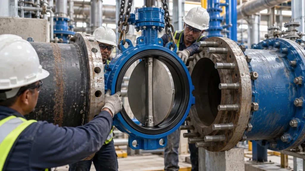
A replacement 6-inch Class 150 gate valve can arrive on site with every tag matching the old one, and still not fit the gap in the line. The flange bolting lines up, the pressure class is right, yet the spool will not close. Nothing was mislabelled. The buyer simply took a number from the wrong table, because a gate valve’s dimensions are not one number and not one standard. It is four groups of measurements, governed by different documents, and the fastest way to order the wrong valve is to treat any of them as interchangeable.

What Gate Valve Dimensions Actually Cover
The phrase covers four separate groups. Face-to-face length for flanged valves, end-to-end length for weld ends: that is the flow interface, and it decides whether the valve drops into the existing gap in the pipe. The bolting interface is flange outside diameter, bolt circle, bolt-hole count and facing. It decides whether the joint can be bolted up at all. Closed height, fully open height, handwheel sweep and any gearbox or actuator body form the operating envelope. This is the group that decides whether the valve physically fits under a pipe rack or beside a pump. Weight and centre of gravity are the handling group, and they decide whether existing supports and lifting gear can take the valve.
Flow interface
Face-to-face (F2F) for flanged ends; end-to-end (ETE) for weld ends; bore size
Bolting interface
Flange OD, bolt circle, hole count, facing (RF/FF/RTJ)
Operating envelope
Closed and open height, stem travel, handwheel, gearbox, actuator body
Handling data
Weight, centre of gravity, lifting points
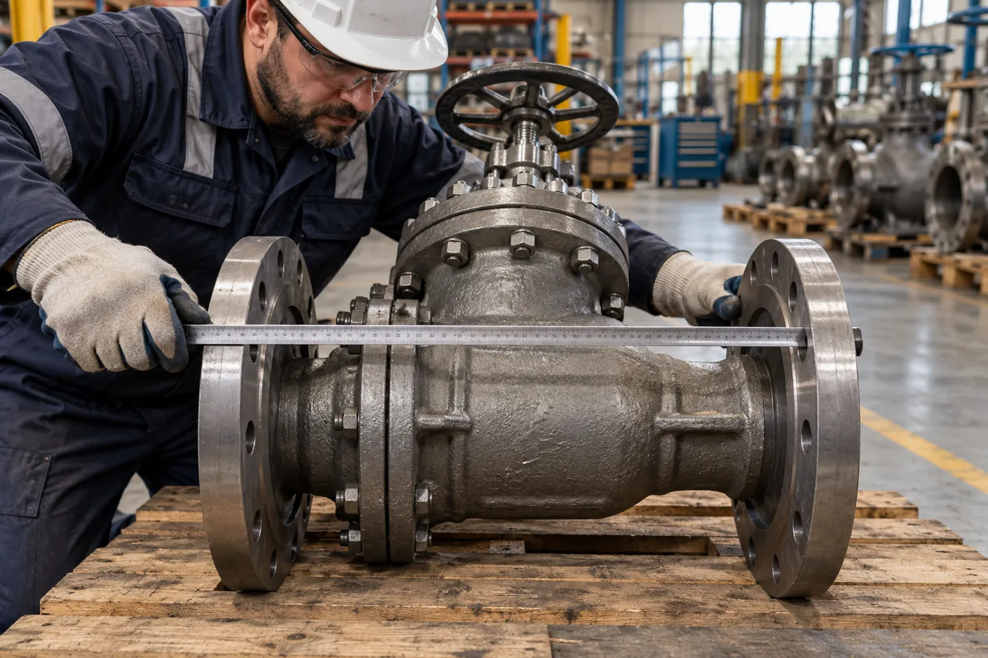
Nominal size is the trap at the centre of this. NPS or DN is an ordering input that points you to a row in a table. It is not a measurement of the valve, and two valves with the same DN can differ in length, height, weight and flange drilling. Among the four groups, the one people check first in replacement work is face-to-face: the axial distance between the two flange end faces, measured along the pipeline centreline. Measure it between the gasket faces, not across the flange rims, and write down which end condition it belongs to before comparing it with any chart.
Face-to-Face Dimensions: Which Standard Gives Which Number
Here is the fact that unsettles most first searches. The same 6-inch Class 150 gate valve is listed at 267 mm face-to-face in the ASME B16.10 tables. The guide that serves most Google results also prints a “Class 150” gate table, and its 6-inch row reads 394 mm. Both tables claim to describe the same valve. The explanation is not exotic. The 394 mm figure is the ball valve long-pattern value from the same standard, copied into a gate table by a source that merged columns. Every number you transfer into an RFQ should be traced back to its column before it is trusted.
267 mm
ASME B16.10, gate column, Class 150 raised face: the real face-to-face
394 mm
Ball valve long-pattern value, printed in a gate table
The ASME B16.10 Industrial Route P
This is the table most plant and process work runs on, so treat it as the default. ASME B16.10 fixes face-to-face and end-to-end lengths for flanged and butt-welded steel valves, including solid wedge and double disc gates. For Class 150 raised-face flanged valves the gate column reads
| NPS (in) | DN (mm) | Class 150 F2F (mm) | Class 300 F2F (mm) |
|---|---|---|---|
| 2 | 50 | 178 | 216 |
| 3 | 80 | 203 | 282 |
| 4 | 100 | 229 | 305 |
| 6 | 150 | 267 | 403 |
| 8 | 200 | 292 | 419 |
| 10 | 250 | 330 | 457 |
| 12 | 300 | 356 | 502 |
Two habits keep this table safe. First, read the class column before the number: Class 300 values are longer because the body is heavier, not because the pipe is bigger. Second, check the facing column: the standard lists raised face, ring joint and weld-end values separately, and they are not the same length for the same valve.
The API 6D Pipeline Route
Pipeline slab and through-conduit gate valves are built for pigging and double block-and-bleed duty, and API 6D governs them (API Spec 6D, 2008). At Class 150 their raised-face face-to-face lengths actually match the ASME table above, 267 mm at 6 inches included (Valve Specifications, n.d.). The divergence appears at the ends. Pipeline valves are most often welded in, and for weld ends the governing figure is end-to-end, not face-to-face: 15.88 in, 403 mm, at 6 inches Class 150. A buyer who takes 267 mm from a flanged column into a weld-end RFQ has just cut the spool a metre-class error short. No tolerance clause covers it: API 6D allows only ą1.5 mm on sizes up to 10 inches.
Waterworks, Knife and Metric Routes
The resilient wedge valves used in water distribution follow the AWWA C509/C515 product route, with their own end and length references. They should never be checked against the steel-industrial table, even when the inch size looks familiar. Knife gate valves, built for pulp, slurry and fibrous media, sit on shorter face-to-face series of their own because the blade gate needs less body length. On the metric side, EN 558 defines European basic face-to-face series that carry their own series numbers. Four routes, four sets of numbers, one nominal size: the route must be fixed before any value is quoted.
| Product route | Governing references | 6 in Class 150 example | End condition premise | What breaks when mixed |
|---|---|---|---|---|
| Industrial wedge gate P | ASME B16.10 (with API 600/B16.34 product standards) | F2F 267 mm (RF) | Flanged RF; RTJ and weld ends have separate columns | Copying the ball long-pattern 394 mm into a gate RFQ puts a 127 mm ghost in the spool |
| Pipeline slab gate | API 6D | F2F 267 mm (RF); ETE 403 mm (weld end) | Weld ends governed by end-to-end | Quoting 267 mm into a weld-end job shortens the spool far beyond the ą1.5 mm tolerance |
| Waterworks resilient wedge | AWWA C509/C515 route | Own end and length references | Ductile iron bodies, Class 125/150 flange practice | Treating an AWWA 6 in valve as a steel-industrial 6 in valve mixes two product families |
| Knife gate | Own short-series F2F tables | Shorter F2F than wedge gates | Wafer and lug style ends | Substituting a knife gate’s length into a wedge gate line alters every spool around it |
The column, the class and the end condition are three separate decisions. Every sourcing error in this topic starts by collapsing two of them into one.
Beyond Face-to-Face: Height, Operators and the Actuated Envelope
A face-to-face match is necessary and not sufficient. The valve occupies a vertical and lateral space too, and that space has no universal table behind it.
Closed Height, Open Height and Stem Travel P
ASME B16.10 does not specify valve height. Closed height and fully open height come from the manufacturer’s general arrangement drawing, and they differ from brand to brand in the same size and class. With a rising stem valve, the fully open height equals the closed height plus one full stem travel. The ceiling, platform or cable tray above the valve must clear the open position, not the closed one.
The valve operates open. Clearing only the closed height is the most common envelope error in retrofit work.
Handwheels and Gearboxes
A handwheel needs its sweep diameter plus room for a gloved grip. Above a certain torque the handwheel gives way to a gearbox, which shortens the wheel sweep but widens and lengthens the body. Both need removal clearance: the handwheel must come off the stem, the gearbox must come off the yoke, and neither is part of any standard dimension table.

The Actuated Envelope
Adding an actuator changes the calculation completely. A multi-turn electric actuator adds height, width and a motor body that needs cooling air and removal space. The attachment interface is standardised. ISO 5210 defines the multi-turn actuator mounting flange and drive dimensions, with designations such as F05 through F16. That means valve and actuator can be mated across brands (ISO 5210:2017, 2017). The standard covers the joint, not the body. The actuator’s outline, its weight and its handwheel override remain manufacturer-specific.
One published multi-turn electric gate valve series
DN50-300bore (2 to 12 in)
10-64 barpressure class
425 °Cmax temperature
50-10,000 Nmactuator torque
IP65 / 67 / 68protection class options
Handwheel overridepower-loss fallback
Those figures describe one series, not a category limit. What transfers is the checklist: torque match, protection class for the install environment, override presence, and the outline drawing that says how tall and how wide the assembly really is.
| Operator | Adds in height | Adds in width | Verify before ordering |
|---|---|---|---|
| Manual handwheel | Full open height, wheel sweep | Minimal | Open-height clearance, grip access |
| Gear operator | Mounting adapter height | Gearbox body | Removal space for the gearbox, input-shaft side |
| Electric multi-turn | Actuator height and stem extension | Motor body width | ISO 5210 flange size, outline drawing, cooling and removal space, override |
Weight, Supports and Lifting
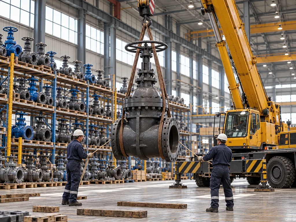
The last envelope number is mass. A replacement valve can match every interface dimension and still weigh substantially more, because wall thickness and class grew. Existing pipe supports, spring hangers and lifting points were sized for the old mass. Ask for the approximate weight with the drawing, and check the supports before the crane is booked.
The boundary for this whole station is one action. Before the rack elevation or the order is fixed, obtain the general arrangement drawing for the exact configuration, manual or actuated. Clear the real envelope, closed and open, against it.
Checking Fit Before You Order: Replacement and RFQ Checklist
Dimension errors are cheap to prevent at the desk and expensive to find at the flange. A first-person QC account from a valve supplier describes the pattern: hours spent on valve-type selection, an RFQ sent with three lines, and a first batch rejected at inspection. The rejection did not happen because the valves were bad. It happened because the dimensional contract was thin.
Run the check in this order:
- Fix the product route and the standard edition. Industrial steel, pipeline, waterworks or knife; the route decides which table exists for you.
- Match the flow interface. Flanged, weld, threaded or wafer; flanged means face-to-face, weld means end-to-end, and the facing (RF, FF, RTJ) must be named.
- Match the bolting interface. Flange OD, bolt circle and drilling come from the flange standards, not from the valve length standard.
- Clear the operating envelope. Closed and fully open height, operator type, actuator outline if any, against the real space.
- Check mass against supports and lifting. Old valve weight is not the new valve weight.
- Sign back the drawing revision. No general arrangement drawing, approved for the configuration, means no order.
An RFQ that survives contact with inspection carries these fields:
| RFQ field | What it pins down |
|---|---|
| Valve design and product route | Wedge, slab, resilient, knife; which family of tables applies |
| Standard and edition | B16.10-2017, API 6D edition, project-specified revision |
| NPS / DN and class or PN | The table row and column |
| End connection and facing | F2F vs ETE; RF, FF, RTJ |
| Face-to-face or end-to-end value | The installation length with its basis named |
| Closed and open height limits | The available envelope, not just the valve |
| Operator type, torque and orientation | Handwheel, gear, electric; which way it faces |
| Protection class and override (actuated) | IP rating, manual fallback |
| Weight limit and lifting points | Supports and cranes |
| Drawing requirement | GA drawing with revision control; 2D/3D files for the model check |
Vendors who can return a versioned GA drawing quickly are worth shortlisting before price is discussed. Suppliers that publish 2D and 3D drawings within 48 hours exist, and that turnaround is a fair benchmark to write into the RFQ.
What This Means for Your Next Valve Order
Three lines on an RFQ do not save time. They move the cost of a thin specification to the receiving inspection. There a 127 mm phantom, copied from a ball valve column into a gate table, becomes a crane booking, a site delay and a re-order. The numbers in this article cost nothing to check: the route, the class, the end condition, the open height, the weight.
So screen suppliers on dimension-file capability first. Ask who can issue a general arrangement drawing with a revision number. Ask who states which standard edition each value comes from. Ask who can supply the same gate valve series with flanged ends to ANSI, DIN, JIS and GB practice. Price comparison belongs after those answers, because a cheaper valve with an unverifiable drawing is the most expensive line item on a project.
For replacement and retrofit work, pull the envelope checks into the RFQ stage. Open height, actuator outline and weight are answerable on paper, and they are unanswerable once the valve is on the truck.
Distributors face the same discipline as a stocking decision: keep the industrial ASME-family series, the waterworks series and the knife gate series separate in the catalogue and in the warehouse. The numbers look similar and are not interchangeable.
We build this range for exactly that kind of checking. Vincer supplies manual flanged gate valves in rising and non-rising stem and multi-turn electric gate valves from DN50 to DN300. The flanged ends match ANSI, DIN, JIS and GB standards, and custom specifications are available on request. If you want to put one supplier’s dimension tables and drawings against your line list, our gate valve range page carries the current series.
Put our dimension tables against your line list
Dimension-checked quotes, GA drawings with revision control, and a supplier that names the standard edition behind every number.
Request a QuoteReferences
- API. “API Specification 6D: Specification for Pipeline Valves.” 2008. https://law.resource.org/pub/us/cfr/ibr/002/api.6d.2008.pdf
- ISO. “ISO 5210:2017 Industrial valves, Multi-turn actuator attachments.” 2017. https://www.iso.org/obp/ui/#iso:std:iso:5210:ed-2:v1:en