
Why Vacuum Technology Is Critical in Battery Manufacturing
In lithium-ion battery production, three invisible enemies determine whether a cell performs reliably for a decade or fails within months: moisture, oxygen, and gas bubbles each capable of degrading electrochemical performance at the parts-per-million level. Vacuum technology is not a supporting utility in battery manufacturing; it is a core process condition that directly governs electrode quality, electrolyte distribution, and long-term cell integrity.
Vacuum serves three irreplaceable functions across the production line. First, it excludes contaminants pulling moisture and oxygen out of electrode pores before they can react with electrolyte salts. Second, it accelerates physical processes lowering solvent boiling points so drying can happen at temperatures that preserve electrode microstructure. Third, it guarantees seal integrity creating the pressure differential needed to detect even micron-sized leaks before a cell leaves the factory. From slurry mixing to end-of-line testing, vacuum appears at no fewer than five critical process nodes, each with distinct pressure, purity, and control requirements. Understanding what happens at each of those nodes and what equipment makes it possible is the focus of this guide.
Vacuum Applications Across the Battery Production Process
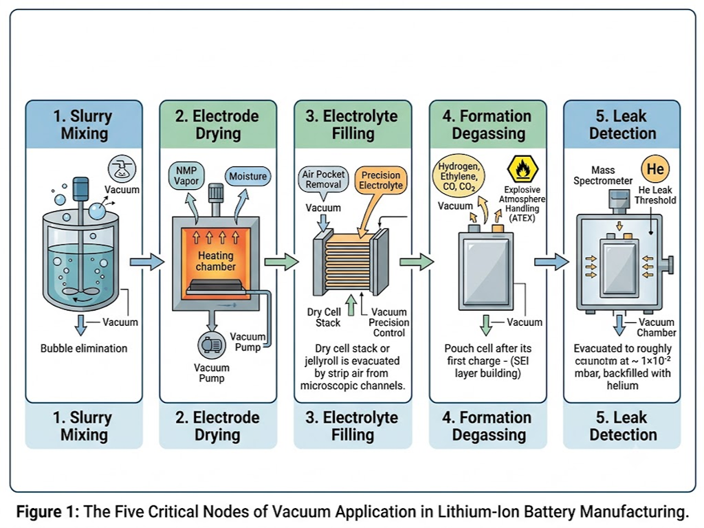
Vacuum in battery production is not one process but five, each solving a different physical problem. The following walks through them in the order they appear on a typical production line.
Process Roadmap
-
1. Slurry Mixing
-
2. Electrode Drying
-
3. Electrolyte Filling
-
4. Formation Degassing
-
5. Leak Detection
Slurry Mixing Eliminating Bubbles Before They Become Defects
Electrode slurry is a viscous suspension of active material powder, conductive carbon, and polymer binder dissolved in N-methyl-2-pyrrolidone (NMP). During mixing, air becomes entrained in the paste and every trapped bubble is a future void in the coated electrode, a site where lithium ions cannot intercalate and capacity is permanently lost.
Vacuum mixing applies roughly -0.09 to -0.095 MPa of negative pressure to draw these bubbles to the surface and rupture them, all while maintaining the shear forces needed for homogeneous particle dispersion. The higher the slurry viscosity as with nickel-rich cathode formulations the longer the required deaeration time, typically 30-50% longer than for LFP chemistries.
Electrode Drying Removing Moisture at the Micron Level
After coating, the electrode web carries residual NMP and trace moisture that must be removed before the cell enters the moisture-intolerant electrolyte filling stage. NMP has a boiling point of 202 °C at atmospheric pressure but heating the electrode to that temperature would degrade the PVDF binder and collapse the carefully engineered pore structure.
Vacuum drying solves this by lowering the boiling point: at pressures below 1 mbar, NMP and water vaporize effectively at 80-140 °C, well within the thermal tolerance of electrode materials. Multi-chamber continuous drying lines process electrode coils in a sequence of vacuum zones, each chamber holding the web for 8-15 minutes. The target residual moisture depends on the chemistry: conventional NMC cells aim for below 300 ppm, while high-nickel and silicon-anode systems push below 100 ppm to prevent hydrofluoric acid generation from LiPF hydrolysis.
Electrolyte Filling Precision Under Vacuum
Electrolyte filling is arguably the most vacuum-sensitive step in the entire production chain. A cell stack or jellyroll contains thousands of microscopic channels between electrode layers and separator pores. Simply pouring electrolyte in at ambient pressure leaves air pockets that block lithium-ion transport pathways every blocked channel is permanently lost capacity.
The procedure is sequential: first, the dry cell is evacuated to roughly 0.01 mbar to strip air from the pore network. Electrolyte is then introduced, and capillary action draws it into the evacuated channels. A final vacuum hold removes residual gas bubbles. The critical parameter here is not just the absolute vacuum level but its stability fluctuations exceeding ±1 mbar during filling can cause electrolyte splatter (if vacuum spikes too high) or incomplete wetting (if it dips too low). Both outcomes send the cell to the reject bin during formation grading.
Formation Degassing Managing the First Charge
The first charge cycle formation builds the solid-electrolyte interphase (SEI) layer on the anode, a passivating film essential for stable cycling. This electrochemical process also generates a cocktail of gases: hydrogen, ethylene, carbon monoxide, and carbon dioxide. In pouch cells, gas evolution can inflate the cell to two to three times its original volume.
Vacuum extraction removes this gas pocket before the cell is final-sealed. Because some of these gases are flammable and the environment contains volatile electrolyte solvents, the vacuum equipment in this zone must meet ATEX Directive 2014/34/EU requirements for explosive atmospheres. After degassing, the cell is sealed under vacuum with a residual internal pressure typically below 50 mbar.
Leak Detection The Final Quality Gate
A battery cell that passes every electrical test can still fail in the field if its housing allows moisture ingress. Helium mass spectrometer leak detection is the industry-standard final check: the cell is placed in a vacuum chamber evacuated to roughly 1×10² mbar, backfilled with helium, and monitored by a mass spectrometer tuned to helium’s characteristic mass-to-charge ratio. The widely adopted rejection threshold is 1 × 10{v mbar·L/s any cell leaking above this rate is scrapped. At this sensitivity, the test can detect a defect smaller than a single bacterium, providing the assurance that the cell’s hermetic seal will hold for the lifetime of the vehicle or device it powers.
Vacuum Pump Technologies and Selection for Battery Manufacturing
Five vacuum processes, five different sets of demands on the pump. Selecting the right pump technology for each process station is the most consequential equipment decision in the vacuum system design.
Dry Pumps vs. Oil-Sealed Pumps The Core Tradeoff
The fundamental divide in vacuum pump technology for battery manufacturing runs between oil-sealed rotary vane pumps and dry-running alternatives (scroll, screw, and claw pumps). The tradeoff is well-understood but the battery context tilts the balance decisively toward dry technology in most process steps.
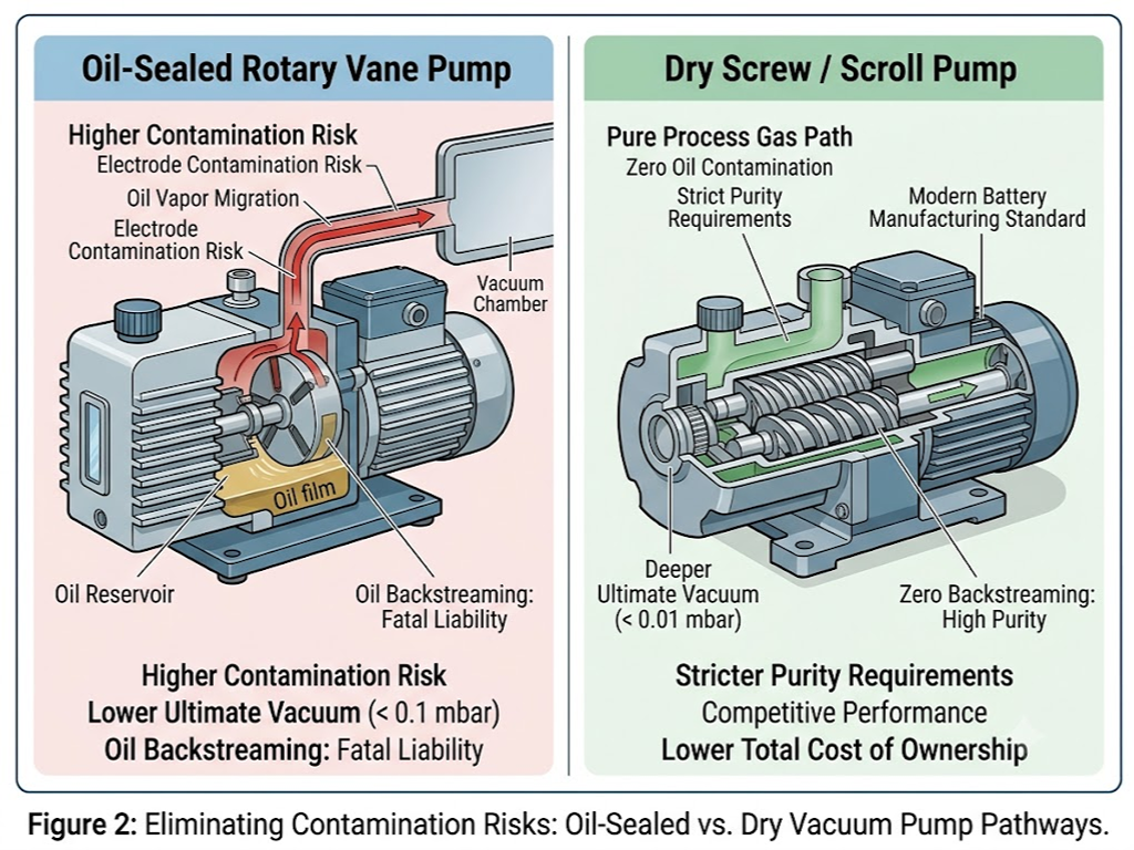
Oil-sealed rotary vane pumps offer deeper ultimate vacuum below 0.1 mbar at a lower initial purchase price. But in battery manufacturing, they carry a fatal liability: oil backstreaming. Even trace oil vapor migrating upstream into a drying chamber or electrolyte filling station contaminates the electrode surface or reacts with LiPF electrolyte salt, creating performance-degrading byproducts. NMP and carbonate solvent vapors also dissolve into the pump oil, requiring monthly oil changes and generating hazardous liquid waste.
Dry pumps screw, scroll, and claw types eliminate oil from the vacuum chamber entirely. Modern dry screw pumps achieve ultimate pressures of 0.01 mbar or better, competitive with oil-sealed designs for all battery processes except specialized high-vacuum applications. Their adoption in battery manufacturing has risen from roughly 30% of new installations a decade ago to over 70% today, driven by stricter purity requirements and lower total cost of ownership when oil disposal and downtime are factored in.
Pump Technology Comparison
-
Oil-Sealed Rotary Vane
-
Ultimate Vacuum: < 0.1 mbar
-
Contamination Risk: Oil backstreaming high risk for electrodes/electrolyte
-
Maintenance: Monthly oil changes; hazardous waste disposal
-
Relative Cost: Lower initial; higher lifecycle (oil + downtime)
-
-
Dry Screw / Scroll
-
Ultimate Vacuum: < 0.01 mbar
-
Contamination Risk: Zero oil no backstreaming; pure process gas path
-
Maintenance: 3 6 month intervals; no oil disposal
-
Relative Cost: Higher initial; lower TCO (adoption 30% -> 70% in 10 yrs)
-
Key Selection Criteria for Battery Applications
Choosing a pump for a specific process step requires evaluating five parameters in order of priority:
-
Target vacuum level and pumping speed. Slurry mixing typically needs 100-500 m³/h of displacement at 10-100 mbar. Electrode drying demands higher throughput 300-1,000 m³/h to handle the large vapor load from evaporating NMP. Electrolyte filling runs at 50-200 m³/h but requires sub-mbar stability. Leak detection chambers are comparatively small, needing only 10-30 m³/h to reach the 1×10² mbar range quickly.
-
Chemical compatibility. The pump’s wetted materials must withstand NMP solvent vapor (which attacks standard elastomers), carbonate-based electrolyte traces (mildly corrosive, hygroscopic), and the mildly acidic byproducts of LiPF decomposition. Stainless steel internals and FFKM (perfluoroelastomer) seals are the baseline specification for any pump handling process gas from drying or filling stations.
-
Temperature tolerance. Drying process exhaust can reach 80-140 °C at the pump inlet. The pump’s internal clearances and seal materials must maintain dimensional stability across this range without binding or leaking.
-
ATEX compliance. Any pump connected to the formation degassing station where flammable gas mixtures are present must carry ATEX certification for Zone 1 or Zone 2 operation, as defined by Directive 2014/34/EU.
-
Total cost of ownership. Energy consumption dominates vacuum system lifecycle costs, accounting for over 70% of TCO. Variable-speed drive (VSD) pumps that modulate motor RPM to match process demand can reduce energy consumption by 30-50% compared to fixed-speed alternatives, typically achieving payback within 18-24 months in continuous production.
Centralized vs. Distributed Vacuum Systems
For plant-level architecture, the choice between distributed pump-per-tool and centralized vacuum networks depends on production scale. Distributed systems where each process station has its own dedicated pump set offer flexibility and fault isolation: a single pump failure does not stop the line. They are the pragmatic choice for pilot lines and factories below roughly 2 GWh annual capacity.
Centralized systems, with a vacuum plant feeding multiple process stations through a piping network, achieve 30-50% higher energy efficiency through pump aggregation and load leveling. At gigafactory scale above 5 GWh per year the energy savings alone justify the higher upfront engineering cost. Centralized designs demand N+1 pump redundancy so that maintenance on one unit never halts production, and the piping network must be engineered to maintain consistent pressure at the farthest station.
Vacuum Valves The Precision Control Layer
If vacuum pumps are the heart of a battery production vacuum system, valves are its nervous system. A typical production line contains hundreds of vacuum valves, and the failure of a single poorly specified valve can shut down an entire process station. Yet valve selection guidance is conspicuously absent from most battery manufacturing literature a gap this section addresses directly.
Types of Vacuum Valves in Battery Production
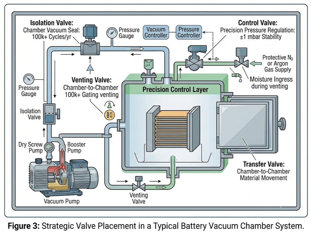
Four valve types handle the majority of vacuum control duties in battery manufacturing, each optimized for a specific function:
-
Isolation valves (gate and angle configurations) seal vacuum chambers from their pumping lines during process steps. In multi-chamber drying lines, they cycle open and closed for every batch transfer accumulating over 100,000 cycles per year. The sealing mechanism must maintain helium-tight closure below 1 × 10{y mbar·L/s leakage even after extended cycling.
-
Control valves predominantly butterfly and proportional types regulate the vacuum level within a process chamber. This is the critical component for electrolyte filling stations. The valve must hold a pressure setpoint stable to within ±1 mbar while the gas load varies as electrolyte wets the electrode stack. Proportional valves offer stepless modulation via electronic control but carry a known reliability concern: extended idle periods can cause the valve spool or throttle plate to stick. This failure mode, documented in battery formation equipment patents, can be mitigated by periodic exercise cycles during production downtimes.
-
Venting valves restore atmospheric pressure after a vacuum process completes. In battery manufacturing, venting is almost always done under a protective nitrogen or argon atmosphere to prevent moisture re-uptake by the freshly dried electrode or electrolyte-filled cell. The valve must handle the pressure differential without generating particle contamination from seat abrasion.
-
Transfer valves move electrode coils or cell stacks between vacuum chambers in continuous processing lines. These are large-aperture designs often rectangular gate valves engineered for the specific dimensions of the production tooling. VAT Group’s 06.6 and 07.7 series, designed for vacuum chamber loading doors, exemplify this category with pressure ratings spanning from 1 × 10{w mbar to over 1 bar absolute.
Valve Types Quick Reference
-
Isolation: Chamber vacuum seal 100k+ cycles/yr
-
Control: Precision pressure regulation ±1 mbar
-
Venting: Restore atm. under N /Ar protection
-
Transfer: Chamber-to-chamber material movement
Material Selection for Corrosive Battery Environments
Battery manufacturing presents an unusually aggressive chemical environment for vacuum valve internals. The material choices that work for semiconductor vacuum where most valve engineering experience originates do not always transfer.
-
Valve body materials. SS316L stainless steel is the default choice, offering adequate corrosion resistance for general vacuum service with its 2-3% molybdenum content providing protection against chloride pitting. For stations directly exposed to LiPF -containing electrolyte vapor which decomposes on contact with moisture to produce trace hydrofluoric acid PTFE or PFA-lined bodies eliminate metallic contact with the process gas entirely.
-
Seal materials. Standard FKM (Viton) elastomers are adequate for general vacuum service up to approximately 200 °C but are not compatible with NMP, which causes over 30% volume swell in standard nitrile and fluorocarbon elastomers. The step-up material is FFKM (perfluoroelastomer, marketed under trade names including Kalrez and Chemraz), which combines near-universal chemical resistance with a continuous service temperature range from -15 °C to over 300 °C. For the highest-temperature drying applications above 250 °C, polyimide diaphragms paired with FFKM O-rings offer the only reliable sealing solution.
-
Materials to avoid. A lesser-known contamination risk in battery manufacturing is metal ion leaching from valve internal components. Copper, zinc, and nickel common in pneumatic valve spools and solenoid components can dissolve in trace amounts into electrolyte or NMP and deposit on electrodes during subsequent process steps, accelerating self-discharge. CKD Corporation’s battery-specific P4 vacuum switching series explicitly restricts these materials from fluid-contact surfaces, a design choice that process engineers should verify when qualifying any valve for battery service.
Valve Reliability and Maintenance in Production Environments
Preventive maintenance for vacuum valves in battery production centers on two tasks: scheduled seal replacement and periodic leak-rate verification. Elastomeric seals have a recommended replacement interval of 6-12 months under continuous production duty; metal-sealed valves extend this to 2-5 years depending on cycle count and process cleanliness.
For diagnostics, the most common failure modes follow a recognizable pattern. A valve that fails to hold vacuum is typically suffering from particulate contamination on the sealing face or pitting corrosion from chemical attack helium leak testing of the isolated valve identifies which. A valve that responds sluggishly or fails to actuate usually points to inadequate pneumatic supply pressure, a failing solenoid pilot, or mechanical binding in the actuator all diagnosable within minutes with a pressure gauge and multimeter. For production lines where a single valve failure can halt output worth thousands of dollars per hour, stocking critical spare valve assemblies rather than individual seal kits is standard practice among experienced maintenance teams.
Common Vacuum Challenges and How to Troubleshoot Them
Vacuum systems in battery production fail in predictable ways. The skill is not in fixing them it is in diagnosing them in the right order, without wasting shifts on the wrong hypothesis.
-
Extended pump-down time the chamber takes longer than baseline to reach its target vacuum. The most common cause is a degraded door or feedthrough seal. Helium leak detection, starting at the largest seals and working inward, localizes the leak faster than trial-and-error seal replacement. If no external leak is found, pump oil contamination (in oil-sealed systems) or internal wear (in dry pumps) is the next suspect a pump-down test on a known-clean reference volume isolates the pump’s own performance from the system.
-
Vacuum level fails to reach setpoint. First, verify the vacuum gauge calibration gauge drift of 10 20% over six months is common and often mistaken for a system fault. If the gauge is accurate, isolate sections of the vacuum manifold with the available isolation valves and measure the leak-up rate of each segment independently. Gradual degradation across all segments points to the pump; a sharp step at one segment identifies a localized leak.
-
Vacuum fluctuation during processing. In electrolyte filling, a pressure signal oscillating more than ±10 mbar around the setpoint usually originates from the control valve either a sticking actuator or a clogged pilot orifice in the electro-pneumatic positioner. Condensed solvent in the vacuum line between the chamber and pump can also cause surging as liquid slugs periodically block and clear the flow path.
Leak Diagnostic Tiers
A practical diagnostic framework uses leak rate as the primary triage metric:
-
< 0.5 (Normal): Trend monitoring only
-
0.5-2.0 (Marginal): Schedule at next downtime
-
2.0-5.0 (Urgent): Intervene this shift
-
5.0 (Critical): Stop production now
The Future of Vacuum Technology in Battery Manufacturing
Three developments are reshaping vacuum requirements for the next generation of battery manufacturing.
-
Solid-state batteries replace the liquid electrolyte with a ceramic or polymer ion conductor a material class that is orders of magnitude more sensitive to moisture and oxygen than conventional liquid electrolytes. Production environments for solid-state cells will demand dry rooms with dew points below -60 °C (versus -40 °C for conventional lithium-ion) and vacuum chambers capable of 10{v mbar base pressure, a full decade lower than today’s electrolyte filling stations.
-
Dry electrode processing eliminates NMP solvent from the slurry entirely a technology pioneered by Maxwell Technologies (acquired by Tesla) and with it removes the largest thermal load on the vacuum system. But the process still requires vacuum for dust control during dry powder mixing and for oxidation prevention during calendering. The vacuum demand shifts from large-volume vapor handling to high-purity environmental control.
-
Intelligent vacuum systems embedding IoT sensors and digital twins represent the near-term efficiency frontier. Real-time pressure, vibration, and power-draw data from every pump and valve feed into a predictive model that schedules maintenance before faults develop and dynamically adjusts pump speed to match production cadence. Early adopters report an additional 20-30% energy reduction beyond what VSD adoption alone achieves.
As vacuum technology in battery manufacturing evolves from a utility to a precision process enabler, the equipment supply chain must keep pace. Manufacturers developing production lines for next-generation cells increasingly seek valve suppliers with deep application-specific engineering capability rather than off-the-shelf catalog parts. For teams evaluating vacuum valve options with tailored material and functional requirements, VINCER’s approach to application-specific valve customization is documented online.
Specify Your Valve Requirements Our engineering team helps you match valve materials and configurations to your battery production process. Request a Quote: https://www.vincervalve.com/contact-for-a-quote/
References
-
GRST International Limited. “Method of Drying Electrode Assemblies.” US Patent 10199635. 2019. (patents.justia.com)
-
Agilent Technologies. “Helium Mass Spectrometer Leak Detection for Li-ion Battery Manufacturing Technical Overview.” 2024. (agilent.com.cn)
-
China SAE / AI Automotive Manufacturing. “Application of Helium Detection Technology in EV Power Battery Manufacturing.” 2024. (caev.org.cn)
-
Leybold GmbH. “Vacuum Systems for Battery Cell Production.” eMobility Engineering. 2023. (emobility-engineering.com)
-
Equilibar. “Lithium-ion Battery Manufacturing Requires Precise Vacuum Control.” 2025. (equilibar.com)
-
VAT Group. “Battery Production Industrial Vacuum Valve Solutions.” 2025. (vatgroup.com)
-
Pfeiffer Vacuum. “Lithium-Ion Battery Manufacturing and Recycling Vacuum Solutions.” 2025. (pfeiffer-vacuum.com)
-
Edwards Vacuum. “Why Dry Pumps Are Better for Li-ion Battery Electrolyte Degassing.” 2025. (edwardsvacuum.com)
-
VINCER Valve. Homepage. (vincervalve.com)
 English
  French
  Spanish
  Italian
  German
  Dutch
Dutch  Portuguese
  Korean
  Russian
  Chinese
  Finnish