In high-stakes industrial piping, selecting the precise bore size is a critical financial and operational decision. Whether prioritizing maximum flow efficiency or controlling capital expenditure, understanding the intricate differences between full bore and reduced bore configurations will heavily impact your system’s performance, energy consumption, and maintenance frequency.
Full Port vs Standard Port Ball Valves: Beyond the Surface Definitions
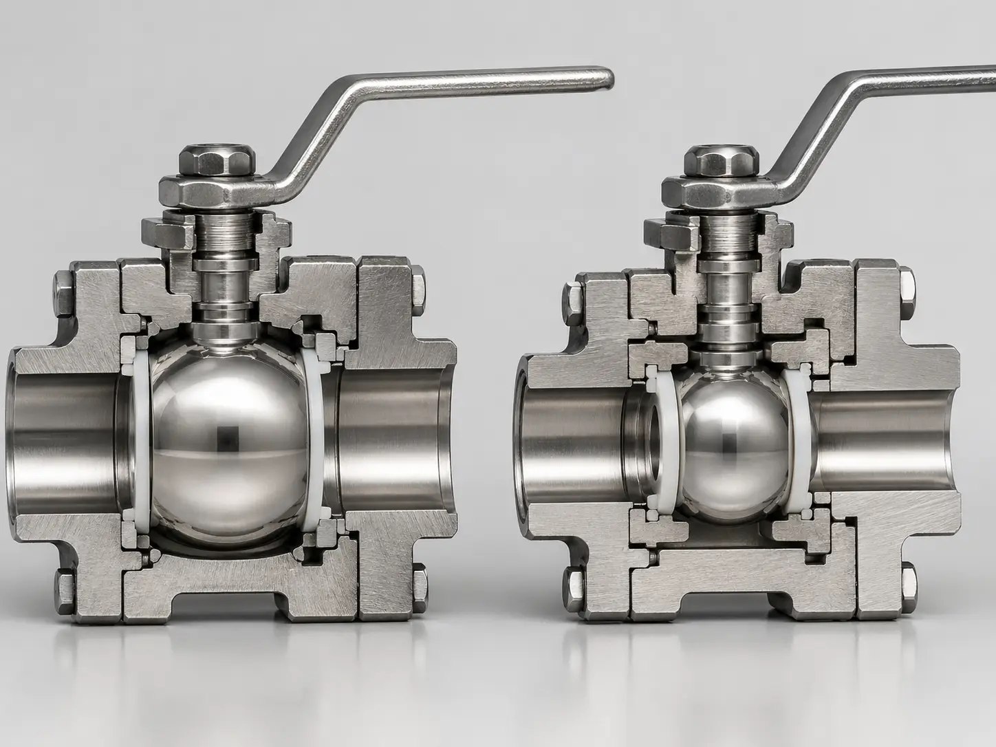
At the very foundation of this engineering debate, the distinction resides in the internal geometric bore size of the valve relative to the connected pipeline’s internal diameter. When evaluating a full port vs standard port configuration, a full port (often referred to as full bore) ball valve features an internal cylindrical opening that perfectly matches the internal diameter of the pipe. This continuous alignment creates a straight, practically unobstructed flow path that acts exactly like a straight piece of pipe when the valve is fully open, maintaining laminar flow and preventing structural bottlenecks.
Conversely, a standard port valve—frequently designated as a reduced port valve within the industry—possesses a ball opening that is restricted in size. The physical housing and the ball itself are smaller, which fundamentally alters the fluid dynamics inside the piping network. Understanding this structural divergence is the first step in avoiding catastrophic misapplications in complex fluid transport systems, where improper sizing can lead to devastating downstream effects.
| Technical Specification | Full Port Ball Valve | Standard (Reduced) Port |
|---|---|---|
| Bore Diameter Geometry | Identical to the connecting Pipe ID | Typically one nominal size smaller than Pipe ID |
| Flow Coefficient (Cv) | Maximum capacity (Minimal frictional resistance) | Significantly reduced capacity (Higher resistance) |
| Pressure Drop (ΔP) | Negligible / Near Zero | Measurable drop due to the Venturi effect |
| Valve Body Footprint | Larger housing, heavier overall weight | Compact geometry, highly space-efficient |
| Initial Capital Cost | Higher material and manufacturing cost | More economical procurement price |
Grasping the nuances of this comparison requires engineers to look far beyond the initial purchase order. While it is true that a standard bore is inherently more economical due to its reduced reliance on raw materials like stainless or carbon steel, it introduces inevitable flow restrictions. The critical engineering task is calculating whether the upfront procurement savings justify the potential long-term energy loss caused by increased pump workload, fluid shear stress, and associated mechanical degradation over the asset’s lifecycle.
The Physics of Flow: Cv Values and Pressure Drop Explained
In fluid dynamics, pipeline efficiency is universally quantified by the Flow Coefficient, commonly known as the Cv value. This metric defines the volume of water (in US gallons per minute) at 60°F that will seamlessly flow through a specific valve while yielding a pressure drop of exactly 1 psi. When executing a rigorous performance comparison between different valve styles, the Cv value stands as the ultimate arbiter of flow efficiency and operational viability.
The functional relationship between the volumetric flow rate (Q), the Flow Coefficient (Cv), and the pressure drop (ΔP) across the valve is mathematically governed by the fluid dynamics formula:
Q = Cv * √(ΔP / SG) (where SG is the Specific Gravity of the fluid).
Because a reduced port physically constricts the cross-sectional flow area, the pressure drop (ΔP) must inevitably increase if the system attempts to maintain a constant flow rate (Q).
Demystifying Flow Coefficient (Cv) in Practical Piping Systems
To transition from theoretical formulas to real-world engineering, let us examine standard industry data. A typical 2-inch full port ball valve usually boasts a massive Cv value ranging between 350 and 450, presenting virtually zero obstruction to the fluid pathway. Conversely, if we evaluate the identical 2-inch nominal pipe size but utilize a standard port design, the Cv value plummets dramatically to a range of 120 to 150.
This represents an astonishing reduction in flow capacity by nearly 60-70%. In a heavy-duty industrial setup, this severe bottleneck forces the system’s centrifugal pumps to work exponentially harder to push the required fluid volume through the constricted bore. This elevates the Reynolds number, shifts the fluid from a laminar to a turbulent state, consumes significantly more electricity, and drastically accelerates the mechanical degradation of pump impellers and seals.
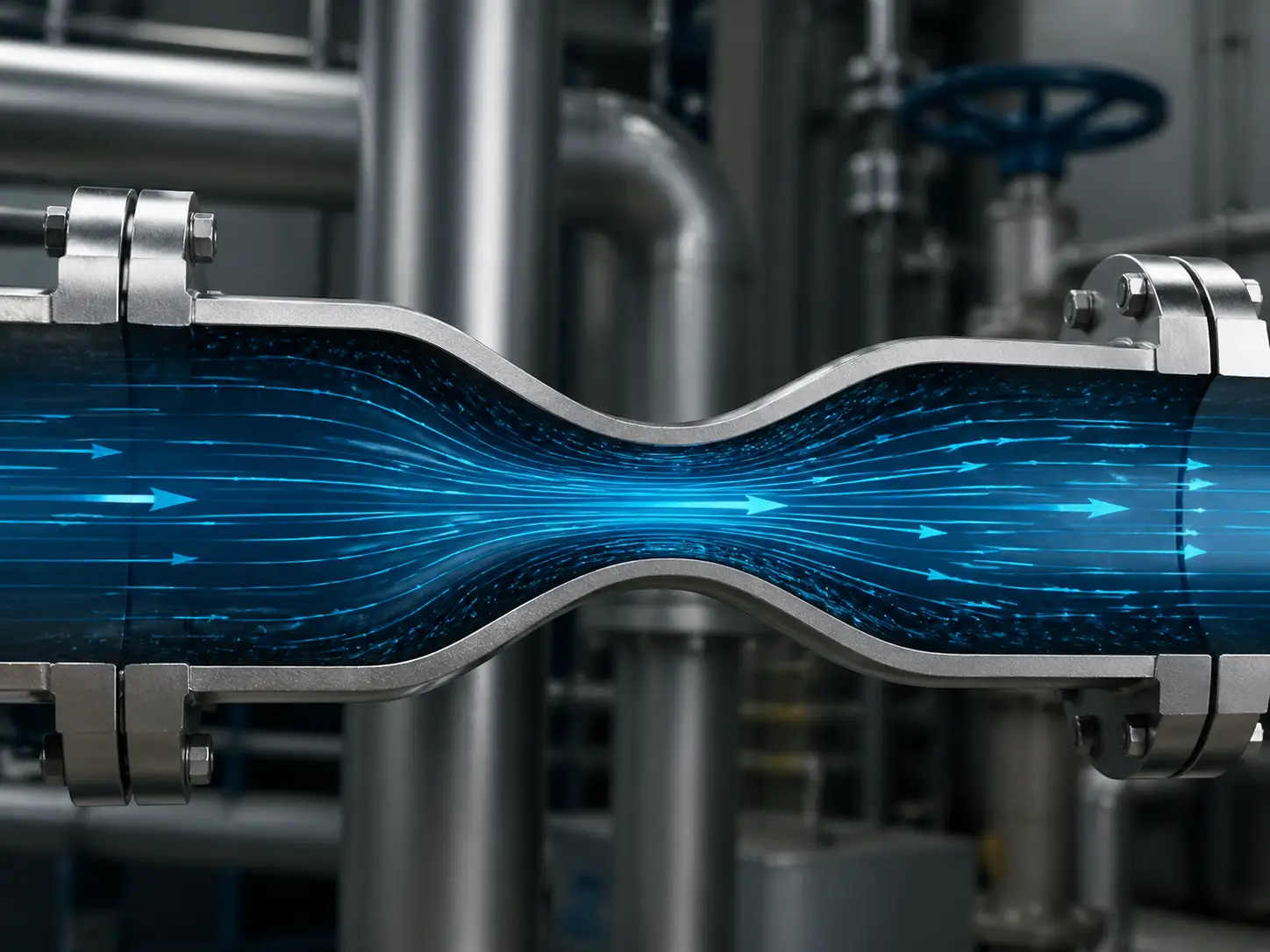
The Venturi Effect and Your Hidden Energy Costs
When high-velocity fluid enters the narrower internal bore of a standard port unit, it experiences forced acceleration—a phenomenon fluid engineers recognize as the Venturi effect. This sudden acceleration simultaneously triggers a localized drop in fluid pressure. If the piping system is operating close to the vapor pressure threshold of the transported liquid, this pressure drop can initiate cavitation.
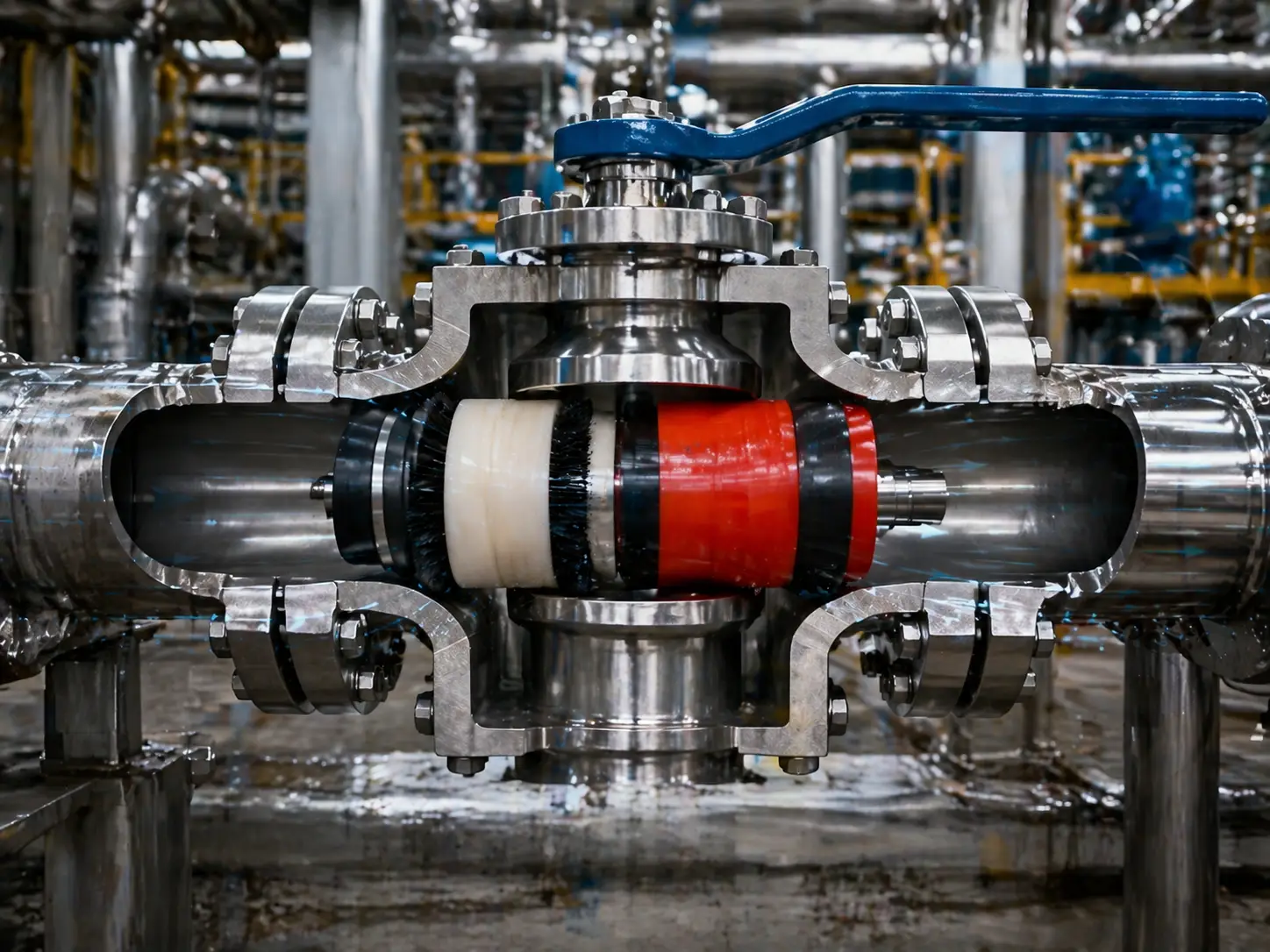
During cavitation, microscopic vapor bubbles rapidly form and then violently collapse against the metal surfaces as the pressure recovers downstream. Over continuous operation cycles, these implosions generate massive shockwaves that erode the valve’s internal metallic components, destroy soft seating materials (like PTFE or PEEK), and lead to premature internal leakage. The energy costs associated with overcoming this pressure drop, combined with the maintenance costs of cavitation damage, easily eclipse the initial savings of buying a smaller valve.
Critical Application Constraints: When You Must Use Full Port
While budget-conscious procurement teams often lean toward reduced bore options due to attractive upfront pricing, certain industrial processes present environments where physical constraints leave absolutely no room for compromise. In these extreme operational envelopes, deploying anything other than a full-bore valve is a guaranteed recipe for systemic failure, hazardous leaks, and unacceptable downtime.
Viscous Fluids, Slurries, and Abrasive Mediums
In demanding sectors such as municipal wastewater treatment, pulp and paper manufacturing, or severe-service mining operations, the transported fluids frequently contain high concentrations of suspended solid particulates or possess extreme dynamic viscosity. In these challenging scenarios, specifying a ball valve full port vs standard port configuration is an absolute necessity.
The geometric restriction inherent in a reduced port valve actively creates stagnation zones within the valve body cavity where thick media can pool, solidify, and ultimately jam the mechanical operation of the ball. Furthermore, the localized velocity spikes caused by the narrower bore force solid particles (like sand, ore slurry, or scale) to act as a high-speed abrasive jet. This fluid shear stress rapidly scours the seats, guaranteeing a drastically shortened lifecycle. Full bore valves maintain a consistent velocity profile, allowing abrasive media to pass through without aggressively attacking the sealing surfaces.
Pipeline Pigging: The Non-Negotiable Industry Requirement
For upstream and midstream oil, natural gas, and complex chemical transportation networks, pipelines require routine mechanical cleaning, fluid separation, and internal inspection through a process known as “pigging.” A pipeline pig is a highly specialized, solid cylindrical device engineered to precisely match the internal diameter of the host pipe.
In this context, the debate regarding bore dimensions is instantly resolved by simple physics. A standard port valve acts as an impenetrable physical barrier; the cleaning pig will forcefully strike the reduced opening of the valve, instantly becoming lodged. Retrieving a stuck pig requires a complete, emergency pipeline shutdown, depressurization, and occasionally cutting into the pipe itself—incurring hundreds of thousands of dollars in unscheduled downtime. Therefore, if a line must be piggable, a full bore design is the only mathematically possible choice.
Strategic Deployments: When a Standard Port is the Superior Choice
It is important to acknowledge that there are highly valid, mathematically sound reasons to select a standard port design. In specialized original equipment manufacturing (OEM), skid-mounted systems, or densely packed chemical mixing modules where spatial real estate is at a massive premium, the compact footprint and substantially lower weight of the standard port design provide massive architectural advantages.
Because it requires less stainless steel or carbon steel casting, it remains the budget-friendly and physically viable choice for transporting clean, low-viscosity utilities like instrument air, potable water, or low-pressure steam where minor pressure drops are structurally irrelevant. In these non-critical utility lines, the turbulence generated by the reduced bore does not threaten the system’s integrity, making the standard port a highly efficient use of capital.
The TCO Trap: Initial Price vs Automation and Actuation Costs
In sophisticated B2B procurement, Total Cost of Ownership (TCO) rules over the initial invoice value. While many engineering discussions begin by exclusively comparing the raw material costs of the valve body, they fatally ignore the most expensive and critical component of modern fluid control: the automated actuator.
Valve Torque Dynamics and the Hidden Cost of Actuators
The financial narrative shifts violently when automation is introduced. The larger, heavier ball inside a full port valve naturally has a vastly expanded surface area that remains in constant, pressurized contact with the valve seats. This increased friction translates directly into a massively elevated “Breakaway Torque”—the raw rotational force required to crack the valve open from a fully closed position against line pressure.
Engineering Methodology: Optimizing the Valve-Actuator Matrix
The torque differential between bore sizes is where procurement budgets often spiral out of control. Upgrading to a full-bore valve for marginal flow gains often forces engineers to exponentially upsize the required pneumatic or electric actuator to overcome the increased breakaway torque. Utilizing a massive rack-and-pinion or scotch-yoke actuator for a simple process line is a prime example of inefficient capital allocation.
To prevent this “TCO Trap,” professional automation integrators like VINCER utilize a proprietary 8-Dimension Analysis Method. Rather than blindly deploying oversized actuators, this engineering methodology comprehensively analyzes specific gravity, working pressure differentials, seat material friction coefficients, available air supply pressure, and safety factors. This approach ensures the actuator is properly sized—preventing expensive “over-actuation” and securing cost-efficiency without sacrificing system reliability.
Industry Standards: ASME B16.34 and API 6D Clarifications
To completely eliminate ambiguity in global procurement, international engineering standards strictly define the geometric thresholds of these components. Whether a facility is sourcing components for a standard utility line or a critical high-pressure hydrocarbon manifold, adherence to standards like ASME B16.34 (Valves—Flanged, Threaded, and Welding End) and API 6D (Specification for Pipeline and Piping Valves) is non-negotiable.
Specifically, ASME B16.34 strictly dictates the acceptable minimum internal bore diameter. Under these rigid guidelines, a reduced port valve is defined by having an internal bore that is exactly one nominal pipe size smaller than the pipeline connection size (e.g., a 3-inch valve with a 2-inch internal bore). Furthermore, API 6D requires full opening valves to provide an unobstructed bore to allow the passage of smart pigs for pipeline inspection. Relying on these rigid definitions ensures that fluid engineers can accurately calculate pressure drops and flow velocities based on legally binding manufacturing characteristics, rather than relying on inconsistent marketing terminology.
4-Step Engineering Decision Tree for Valve Selection
Navigating the complex matrix of flow coefficients, torque ratings, standards, and upfront costs does not have to paralyze your project timeline. Utilize this pragmatic, data-driven decision tree to determine the optimal configuration for your specific piping network:
- Step 1: Analyze the Medium Profile. Does the fluid contain abrasive suspended solids, high viscosity, or thick slurries? If yes, mandate Full Port to prevent mechanical jamming and seat erosion. If it is a clean liquid or gas, proceed to Step 2.
- Step 2: Verify Pigging and Cleaning Requirements. Will the pipeline ever require mechanical pigging for cleaning, batch separation, or API 6D smart pig inspections? If yes, Full Port is 100% physically required. If no, proceed to Step 3.
- Step 3: Evaluate Pumping Power and Velocity Parameters. Calculate the system’s baseline parameters. If your continuous liquid velocity exceeds 10 to 15 feet per second (ft/s), or if the associated centrifugal pump operates on a relentless 24/7 duty cycle, the cumulative electrical energy losses caused by the pressure drop of a standard port valve will rapidly overshadow any initial capital savings. In these high-duty scenarios, Full Port is the mathematically sound choice.
- Step 4: Audit Automation Budget and Spatial Footprint. If you survived the first three steps, you can safely utilize a Standard Port valve. Enjoy the benefits of a smaller installation footprint, lighter pipe load, and the ability to specify a smaller, more economical automated actuator due to the lower torque requirements.
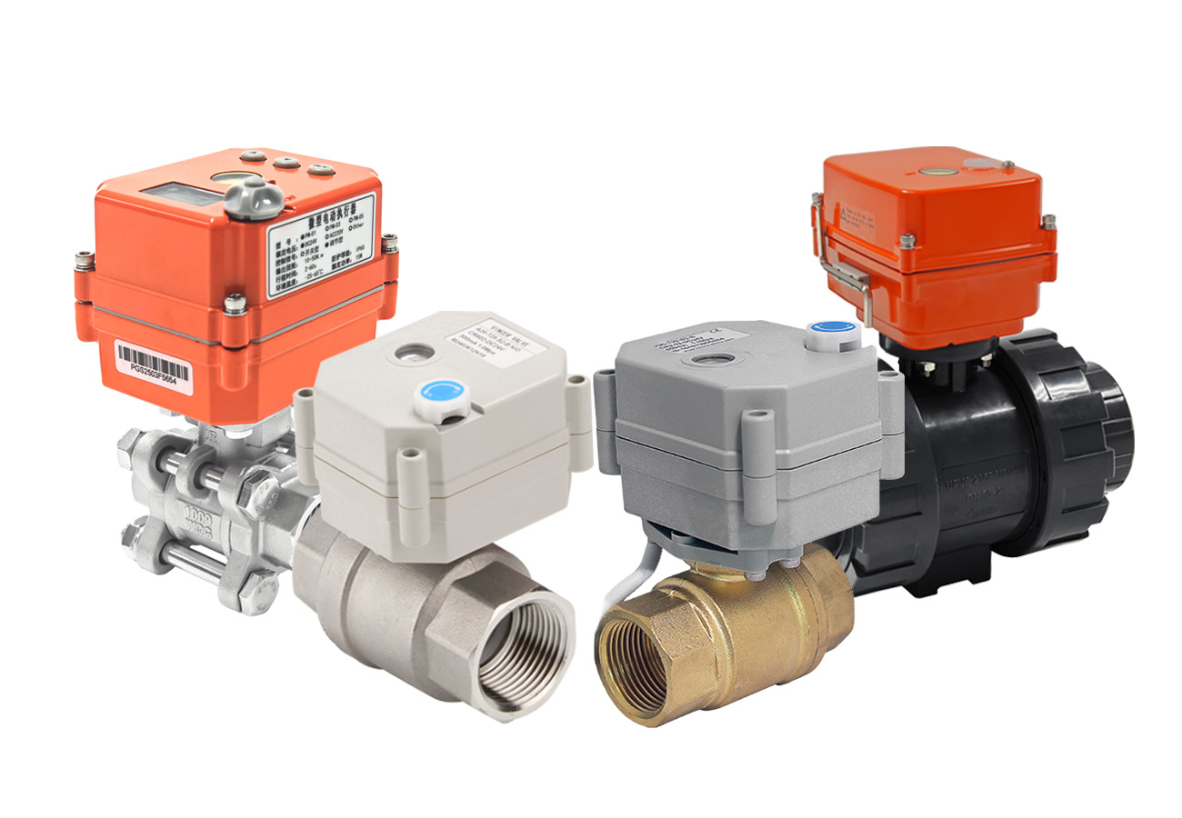
Transitioning to Automated Control Systems
Successfully determining the correct bore size using the decision tree is an important step. Another critical consideration is how the valve will be operated within your facility. While manual valves are highly reliable for basic applications, they present practical limitations in complex systems—such as desalination, chemical processing, or extensive manufacturing lines. In these environments, manual operation can struggle to provide the rapid response times needed during pressure changes, and it lacks the ability to integrate with centralized PLC or SCADA systems for real-time monitoring and remote control.
Upgrading to actuated valves (electric or pneumatic) addresses these specific operational needs. Automated control ensures consistent torque application, facilitates immediate remote adjustments, and reduces the manual labor required for routine line operations.
If your project parameters suggest a transition to automated fluid control, VINCER VALVE is equipped to support your requirements. With over 10 years of experience in the automated valve sector, we focus on providing properly calibrated solutions rather than simply supplying hardware.
- Torque Matching: We apply an 8-Dimension Analysis Method to match the actuator to your specific working pressure and medium, ensuring the system operates efficiently without over-specification.
- Standard Delivery Timeline: Our conventional automated valve assemblies are typically calibrated and dispatched within 7-10 working days.
- Integrated Packages: We supply complete, pre-tested automated setups, including necessary positioners, limit switches, and solenoid valves for straightforward installation.
If you are evaluating automated valve options for your pipeline, our engineering team is available to assist.