The Hidden Costs of Fragmented Fluid Networks
Industry data reveals a counter-intuitive reality within modern manufacturing: the vast majority of catastrophic industrial fluid system failures—and the resulting millions of dollars in unplanned downtime—do not stem from defective manufacturing of individual parts. Instead, they originate from fundamental design and specification mismatches. When process engineers merely assemble isolated components rather than architecting a cohesive, scientifically grounded fluid dynamics strategy, the financial bleeding remains entirely invisible until the pipeline unexpectedly goes offline.
For plant managers, automation directors, and procurement leaders, the stakes are binary. You are either engineering a resilient cardiovascular system for your facility, or you are unwittingly installing a countdown to your next critical hazardous leak. This comprehensive blueprint strips away generic, high-level advice to deliver a hardcore engineering framework: how to master complex fluid rheology, size pumps using precise hydraulic mathematics, navigate the intricate metallurgy of control valves, and surgically mitigate the hidden operational expenditures (OPEX) that continuously inflate your Total Cost of Ownership (TCO).
The Paradigm Shift: From Isolated Components to Integrated Fluid Handling Solutions
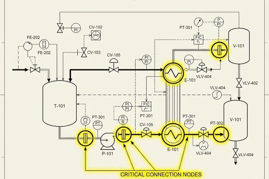
For decades, a highly fragmented approach dominated industrial procurement. Design engineers would source a high-efficiency centrifugal pump from one vendor, automated fluid handling valves from another, and piping networks from a third, operating under the assumption that assembling top-tier parts would naturally result in a top-tier functional network. This archaic mindset frequently leads to what veteran engineers call a “System Bottleneck.” A processing facility is only as reliable as its weakest, most poorly specified junction point.
Consider the vascular analogy. You can possess a remarkably strong heart (the pump), but if your arteries (the piping metallurgy) are severely calcified or your heart valves fail to regulate pressure precisely, the entire biological system faces imminent collapse. In an industrial context, deploying a high-capacity pump alongside an undersized or slowly reacting automated valve will inevitably induce severe water hammer. According to the Joukowsky equation, the sudden kinetic shockwaves generated by rapid valve closure can spike internal pipe pressures by hundreds of PSI in milliseconds. These hydraulic transients can literally tear steel piping supports from concrete walls, shatter expensive mechanical seals, and rupture delicate instrumentation lines.
Therefore, modern fluid handling solutions are not defined by the individual physical specifications printed on a singular product datasheet. Instead, they are defined by the seamless, synergistic interaction of the entire closed-loop control architecture. Adopting this integrated paradigm shifts the engineering focus from simply “moving liquids” to orchestrating a highly controlled, predictive, and safe fluid transfer environment.
Decoding Fluid Dynamics: The Blueprint for Equipment Selection
Before any hardware is specified, CAD drawings rendered, or purchase orders signed, an engineer must possess a granular, molecular-level understanding of the media being transported. Equipment selection is never dictated by the available capital budget alone; it is entirely subservient to the physical, chemical, and thermal “temperament” of the process fluids. Failing to respect the immutable laws of fluid dynamics is the root cause of premature asset degradation.
Managing High-Viscosity and Shear-Sensitive Fluids
Viscosity—the measure of a fluid’s internal resistance to gradual deformation by shear stress or tensile stress—drastically alters how fluid processing equipment must be architected. As dynamic viscosity increases, the internal friction within the fluid skyrockets. This fundamental change alters the Reynolds number of the system, pushing the fluid flow from a chaotic turbulent state into a highly predictable but incredibly difficult-to-move laminar state. In laminar flow regimes, standard centrifugal forces become highly inefficient, converting input energy into destructive heat rather than kinetic movement.
Furthermore, many complex industrial media exhibit Non-Newtonian behaviors. Shear-thinning (pseudoplastic) fluids, such as ketchup, polymer melts, or specific industrial paints, decrease in viscosity under mechanical stress. Conversely, shear-thickening (dilatant) fluids, like concentrated cornstarch suspensions or specific chemical slurries, become nearly solid when agitated. If a plant manager blindly installs a high-speed impeller pump to transfer shear-sensitive emulsions—such as premium cosmetic creams, delicate biopharmaceutical proteins, or complex food additives—the excessive mechanical agitation will permanently destroy the molecular structure of the batch. This results in irreversible product separation, massive yield loss, and ruined production runs.
Conquering Aggressive, Corrosive, and Abrasive Mediums
When engineering industrial fluid handling systems for the chemical processing, semiconductor manufacturing, or modern electric vehicle (EV) battery sectors, the primary enemy is aggressive material degradation. Utilizing standard 316L stainless steel in a high-chloride environment or a concentrated hydrochloric acid line is a costly engineering miscalculation; microscopic pitting corrosion and stress corrosion cracking (SCC) will rapidly compromise the pipeline’s structural integrity, leading to hazardous environmental leaks. Additionally, introducing freezing cold liquids into actively hot pipelines induces severe Thermal Shock, necessitating advanced mechanical stress compensation solutions like metallic corrugated expansion joints integrated directly into the piping network.
To combat purely chemical attacks, elite engineering designs leverage advanced fluoropolymers. Fully PTFE (Polytetrafluoroethylene) or PFA-lined valves provide near-universal chemical inertness, shielding the outer metal body from the corrosive media. However, it is a well-documented industrial reality that standard fluorine-lined components exhibit extremely poor mechanical wear resistance. If the corrosive medium also contains abrasive solid particulates—such as lithium slurries, titanium dioxide, or mining tailings—a standard PTFE lining will be rapidly shredded by the high-velocity solids.
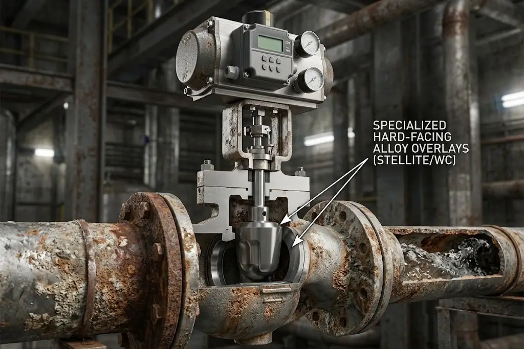
For these dual-threat (high-corrosion plus high-abrasion) environments, the ultimate solution shifts away from soft polymeric linings. Engineers must specify engineered structural ceramic components, or utilize hard-facing alloy overlays—such as Stellite welding or tungsten carbide coatings—on the metallic trims and seats. This surgical material matching, while initially more complex to specify, extends the asset’s lifecycle by massive multiples compared to generic alternatives, ensuring long-term operational stability.
The Heart of the System: Advanced Pump Technologies and Sizing Logic
The pump serves as the prime kinetic mover of the entire operation. However, specifying a pump is an intricate mathematical exercise requiring deep computational analysis of the entire piping network. Moving from fundamental physics to actionable engineering logic requires navigating complex hydraulic parameters to ensure maximum efficiency, optimal flow rates, and extended equipment longevity.
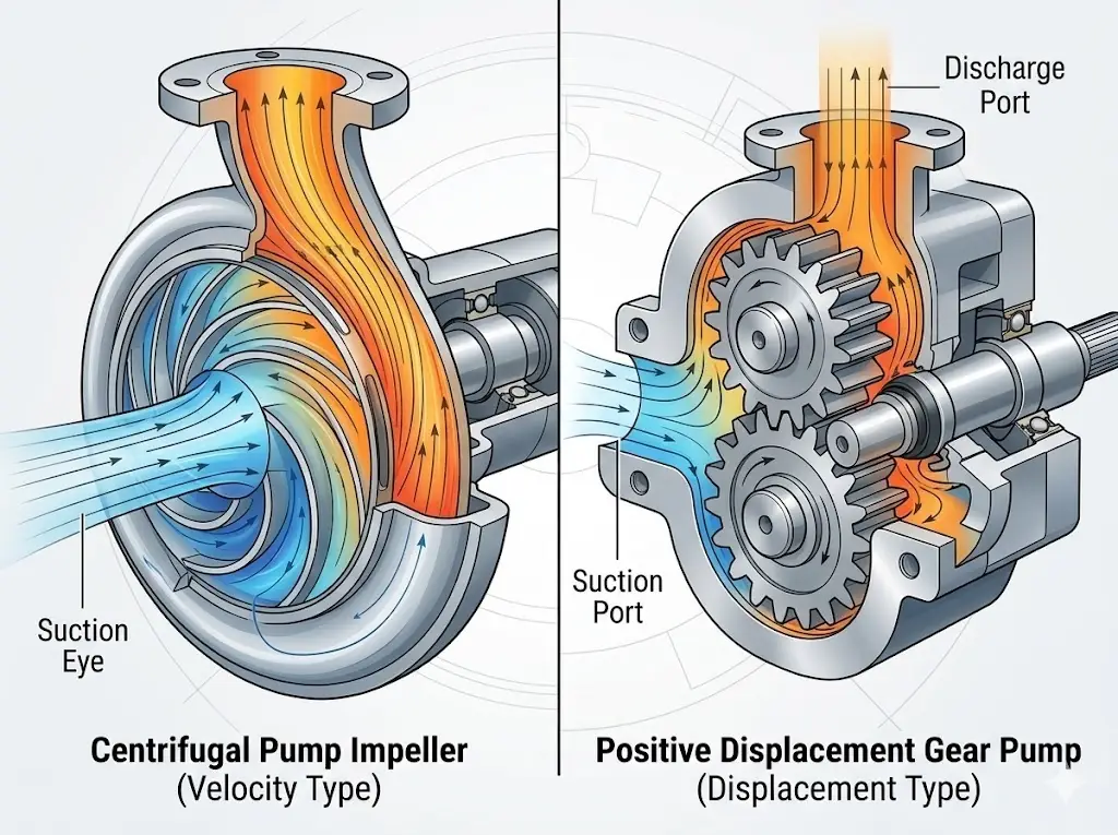
Centrifugal vs. Positive Displacement (PD) Pumps: The Golden Rule
The fundamental bifurcation in pump selection lies between Centrifugal and Positive Displacement (PD) architectures. The golden engineering rule dictates a highly specific decision tree. If the application requires transferring high volumes of low-viscosity fluids at relatively low and stable pressures, a Centrifugal pump is the optimal choice. Centrifugal pumps rely on rotational kinetic energy, transferring momentum to the fluid via a spinning impeller. Conversely, if the process demands the precise, metered flow of highly viscous materials against variable or extremely high system pressures, a PD pump (such as a rotary lobe, internal gear, or progressive cavity pump) is absolutely mandatory.
Selecting oversized centrifugal pumps under the assumption that higher horsepower automatically equates to better performance is a classic, costly novice error. This violates the critical concept of the Best Efficiency Point (BEP). Forcing a centrifugal pump to operate continuously on the far left or right of its engineered performance curve induces severe radial thrust. This unbalanced hydraulic force deflects the pump shaft, destroying mechanical seals and leading to premature bearing failure. Engineers must utilize the Affinity Laws to precisely calculate how changes in impeller diameter or rotational speed will impact flow rate, head pressure, and overall power consumption.
The Hidden Killer: Demystifying Cavitation and NPSH
Even perfectly specified and manufactured pumps can destroy themselves within weeks if the suction-side hydraulics of the facility are poorly designed. Cavitation is the silent, relentless killer of fluid networks. Dictated by Bernoulli’s principle, cavitation occurs when the absolute pressure of the fluid at the eye of the pump impeller drops below the fluid’s specific vapor pressure at that operating temperature.
When this localized pressure drop occurs, the liquid instantaneously boils, forming microscopic vapor bubbles. As these bubbles travel further into the higher-pressure zones within the pump volute, they cannot sustain their gaseous state and violently implode. To an operator walking the plant floor, active cavitation sounds exactly like pumping gravel or marbles through a steel pipe. To the equipment itself, it acts like microscopic explosives, rapidly pitting, eroding, and eventually destroying solid metal impellers.
The Essential Hydraulic Equation
To definitively prevent cavitation, the engineering design must adhere strictly to Net Positive Suction Head (NPSH) calculations. The unyielding rule is:
NPSHa > NPSHr + 0.5m (Safety Margin)
Net Positive Suction Head Available (NPSHa), dictated by atmospheric pressure, fluid temperature, and suction piping friction, must always comfortably exceed the Net Positive Suction Head Required (NPSHr) dictated by the pump manufacturer’s rigorous testing data.
Precision and Isolation: Architecting Valves, Piping, and Sealing
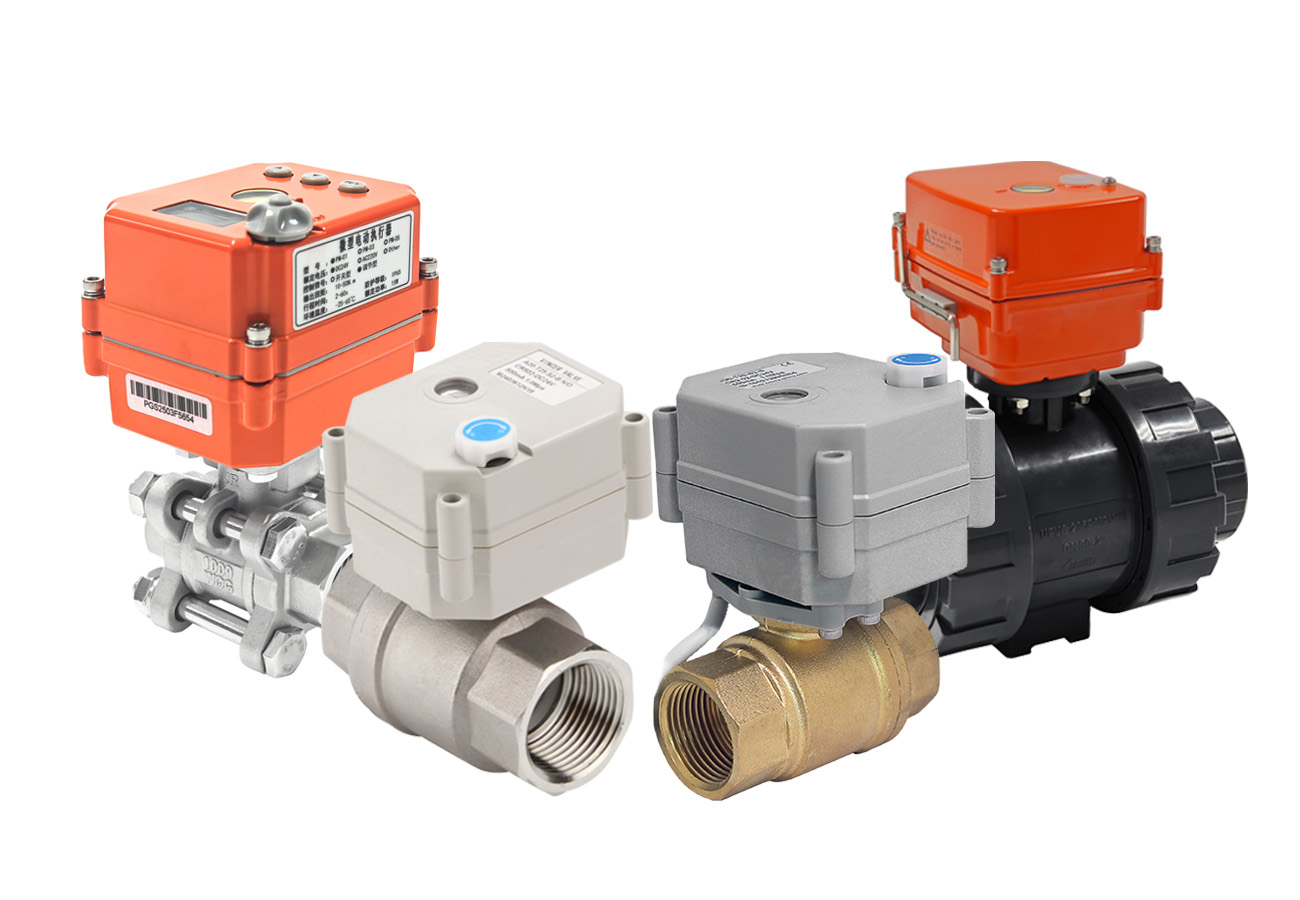
While the pump provides the brute kinetic energy, the intelligence, safety, and ultimate precision of any fluid handling system reside entirely in its peripheral components. Valves are the physical executors of your control strategy. Specifying control valves requires a deep dive into aerodynamic and hydrodynamic flow characteristics. Engineers must meticulously determine whether a process requires the linear flow progression of a globe valve, the rapid quarter-turn isolation of a trunnion-mounted ball valve, or the high-capacity, equal-percentage throttling of a triple-offset butterfly valve. An incorrectly sized control valve—such as one operating constantly below 10% of its stroke—will suffer from severe wire-drawing (erosive wear on the seat) and erratic flow control.
Furthermore, the sealing mechanisms—specifically the packing gland and stem seals—must strictly adhere to the latest low fugitive emission standards, such as API 624 or API 641. These stringent testing protocols ensure that hazardous volatile organic compounds (VOCs) and greenhouse gases do not escape into the atmosphere under high-cycle mechanical operations, safeguarding both personnel and corporate environmental compliance.
The Objective 8-Dimensional Analysis Framework
Valve misapplication is the leading cause of fugitive emissions, jammed pneumatic actuators, and premature stem wear. To mathematically eliminate this engineering risk, top-tier system integrators utilize a rigorous 8-Dimensional Analysis Framework prior to finalizing any equipment selection. This methodology cross-examines:
- Medium Composition: pH levels, solid particulate concentration, and specific phase state.
- Operating Temperature: Continuous operating temps, peak spikes, and thermal shock parameters.
- System Pressure: Dynamic flow pressure drops (ΔP) and maximum static shut-off pressure.
- Connection Standards: Flanged (ANSI/DIN/JIS), fully welded, or threaded.
- Control Method: Pneumatic, electric, or modulating with smart positioners.
- Body and Trim Material: Precise metallurgy for the shell and specific elastomers for seating.
- Industry-Specific Certifications: FDA, API, ATEX, SIL requirements.
- Physical Installation Space: Envelope constraints and maintenance accessibility.
For instance, when processing 170°C heat transfer fluids (thermal oil), a novice might specify a standard ball valve with RPTFE soft seats. Under continuous thermal cycling, the RPTFE will rapidly degrade, extrude, and leak. Applying this 8-dimensional matrix instantly flags the thermal shock and extrusion risk, directly specifying a bellows seal globe valve or a metal-seated ball valve with live-loaded graphite packing. This surgical precision in component matching mitigates the vast majority of downstream leakage and emergency maintenance contingencies.
The Smart Factory Era: IoT Integration and Automated Fluid Control
The era of Industry 4.0 has elevated plant safety and efficiency from passive mechanical boundaries (relying solely on thicker steel) to active, intelligent, and digital monitoring. Legacy fluid systems act as silent, dumb gatekeepers; operators only discover a valve stem is seized when a critical emergency shutdown (ESD) occurs and the valve physically fails to close. Today’s smart automation integrates Partial Stroke Testing (PST) logic directly into the fluid handling technology.
Intelligent electro-pneumatic positioners automatically move the valve stem a micro-percentage (e.g., 5 degrees) during normal operations—without interrupting the flow of process fluids—to continuously verify mechanical integrity. If the pneumatic thrust or torque required to move the stem spikes, indicating friction from crystallizing fluids or failing packing, the system immediately sends predictive maintenance alerts to the central SCADA (Supervisory Control and Data Acquisition) or DCS (Distributed Control System). This allows technicians to resolve the mechanical friction issue weeks before it culminates in an operational failure. By integrating advanced IoT vibration sensors on pump casings and intelligent diagnostics on valve actuators, facilities transition from reactive firefighting to predictive asset management.
Navigating Rigorous Compliance and Safety Standards
In the highly regulated realm of fluid processing, compliance is not a bureaucratic hurdle to be bypassed; it is a literal engineering firewall against catastrophic industrial accidents, environmental disasters, and crippling legal liabilities. Designing a high-pressure system without an obsessive focus on global metallurgical and safety standards is an unacceptable risk. From ISO 10423 / API 6A specifications governing extreme high-pressure wellhead equipment to the delicate sanitary mandates of biotechnology, the specific industry you operate in dictates the fundamental structural DNA of your fluid network.
Oil, Gas & Energy: Conquering High-Pressure and Sour Environments
The global energy and petrochemical sectors operate at the absolute physical limits of modern material science. For these severe applications, strict compliance with API 6D is non-negotiable. Furthermore, any components exposed to aqueous hydrogen sulfide (H2S) must strictly adhere to NACE MR0175 / ISO 15156 metallurgical standards. This standard regulates the maximum hardness of the steel to prevent Sulfide Stress Cracking (SSC)—a terrifying phenomenon where high-tensile steel becomes embrittled by hydrogen atoms and catastrophically fractures. Additionally, API 607 and API 6FA fire-safe testing protocols ensure that if a facility experiences a massive hydrocarbon fire and the primary soft elastomer valve seals melt away, a secondary metal-to-metal seal will mechanically engage, trapping the flammable process fluids inside the pipe.
Food, Beverage & Pharma: Ensuring Absolute Aseptic Purity
In bioprocessing, vaccine manufacturing, and modern food production, a fluid handling system must be flawlessly cleanable without disassembly. The core engineering challenge is the complete elimination of “Dead Legs”—stagnant sections of piping or valve cavities where fluid velocity drops to zero, allowing media to evade the turbulent flow of CIP cleaning chemicals and become a breeding ground for microbial colonies.
To operate legally and safely, every wetted component must meet the rigorous criteria of ASME BPE (Bioprocessing Equipment) and FDA 21 CFR regulations. A single poorly specified diaphragm valve that harbors bacteria due to non-compliant internal drainability can trigger the contamination of an entire batch of life-saving antibiotics or infant formula, resulting in millions of dollars in scrapped product, brand destruction, and severe regulatory penalties from the FDA.
Chemical Processing: The Science of Corrosion Resistance and Explosion-Proofing
Chemical manufacturing plants demand a relentless dual focus: surviving extremely aggressive internal fluid corrosion while maintaining absolute external environmental safety. When transporting highly volatile solvents, the surrounding atmospheric zones are frequently saturated with explosive fumes or combustible dust.
Therefore, any automated fluid control modules or electric actuators deployed in these hazardous zones must carry ATEX or IECEx explosion-proof certifications. It is a common misconception that an “explosion-proof” enclosure is physically indestructible. In reality, the certification guarantees that if an internal electrical short circuit ignites a flammable gas mixture inside the actuator casing, the heavy-duty machined flame paths will completely contain the internal explosion. These precisely engineered gaps cool the escaping hot gases below the auto-ignition temperature of the external atmosphere, preventing a chain-reaction explosion across the facility.
Total Cost of Ownership (TCO): Evaluating Fluid Handling Partners
When the intricate engineering physics, fluid rheology, and rigorous compliance matrices are finalized, the decision ultimately transitions from the engineering schematic to the executive boardroom. In this domain, the most dangerous metric a procurement team can focus on is the initial hardware purchase price. Elite procurement directors and plant managers utilize the Total Cost of Ownership (TCO) Iceberg Model to evaluate long-term financial viability and system resilience.
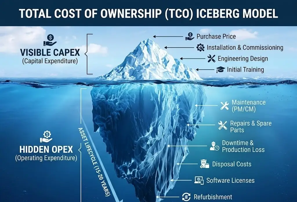
The highly visible tip of the iceberg—the capital expenditure (CapEx) required to purchase the automated valves, pneumatic actuators, electric actuators and centrifugal pumps—rarely accounts for the majority of the system’s true lifetime cost. The massive, hidden bulk submerged below the financial surface consists of continuous energy consumption, routine maintenance labor, the frequent replacement of degraded internal seals, and, most critically, the devastating financial impact of unplanned process downtime. In chemical processing or offshore environments, a single hour of halted production due to a seized valve stem can obliterate months of savings achieved through budget-oriented procurement.
An anonymized case study at a specialty high-corrosion chemical plant vividly illustrates this engineering-to-finance principle. The plant was experiencing frequent elastomer failures on standard 316L stainless steel butterfly valves handling a mild acidic slurry. By applying a rigorous, data-driven analysis matrix, the engineering team decided to upgrade the entire line to fully PFA-lined valves equipped with engineered ceramic trims. Initially, the procurement department resisted, noting that the CapEx for the new, highly specialized valves was visibly higher than their standard commercial replacements. However, this calculated engineering decision extended the maintenance replacement cycle from a mere six months to over three years of continuous, leak-free operation. By drastically reducing replacement labor, eliminating the cost of scrapped contaminated batches, and increasing overall plant uptime, this initial premium ultimately reduced the specific pipeline’s Total Cost of Ownership (TCO) by a highly significant margin, proving irrefutably that superior engineering pays for itself over the asset lifecycle.
The Vincer Valve Advantage: Eliminating OPEX at the Root
Optimizing TCO requires an expert partner who actively engineers operational risk out of your system before manufacturing begins. Founded in 2010, Vincer Valve is a national high-tech enterprise dedicated to providing comprehensive intelligent fluid control solutions. With over a decade of specialized industry experience, Vincer utilizes a rigorous 8-Dimensional Analysis Framework (evaluating medium, temperature, pressure, connection standard, control method, material, industry specifics, and installation space) to select the precise metallurgy and actuation logic for your specific requirements. This engineering-first approach directly mitigates the vast majority of hidden operational expenditures by ensuring the hardware is perfectly matched to the fluid dynamics from day one.
Furthermore, Vincer operates a 7,200-square-meter vertically integrated manufacturing facility equipped with an advanced CNC machining matrix. This autonomous production capability allows the delivery of fully certified (CE, SIL, FDA, ISO9001) electric and pneumatic fluid control solutions with remarkable efficiency. Standard fluid control products are typically delivered in just 7 to 10 working days, while complex customized solutions are engineered and shipped in 15 to 30 days. By streamlining production and offering a comprehensive product portfolio, Vincer consistently delivers highly competitive CapEx optimization while guaranteeing that your critical engineering projects stay strictly on schedule. Ultimately, partnering with Vincer empowers your facility to save project costs and “do more with less.”
Stop Compromising Between Quality and Budget
If you are engineering a critical fluid network and require valve solutions that refuse to compromise on safety while aggressively optimizing your project’s TCO, our engineering team is ready to analyze your parameters.