Ask a piping engineer what a ball valve is and they will say the same thing as a DIY homeowner, just in fewer words. A rotating ball with a hole through it opens and closes flow with a quarter turn. The description is right, and it hides almost everything that matters. The ball does not seal anything by itself. The seat does. The pressure does. And the moment you understand that, every ball valve failure you will ever see becomes predictable: low-pressure weeping, seat wear after years of service, actuators that “lose their grip”.
This article walks through the working principle in the order a buyer actually meets it: the parts, the real sealing mechanism, and the full map of ball valve types — from the two most common designs to the structural layers behind them. We then compare manual and actuated operation, the pneumatic and electric actuators behind automation, and the failure modes that follow directly from the physics. Along the way we flag the boundary conditions that most guides skip. Those boundaries are where buying decisions are made.
What Is a Ball Valve? The Four Parts Behind the Quarter-Turn Principle
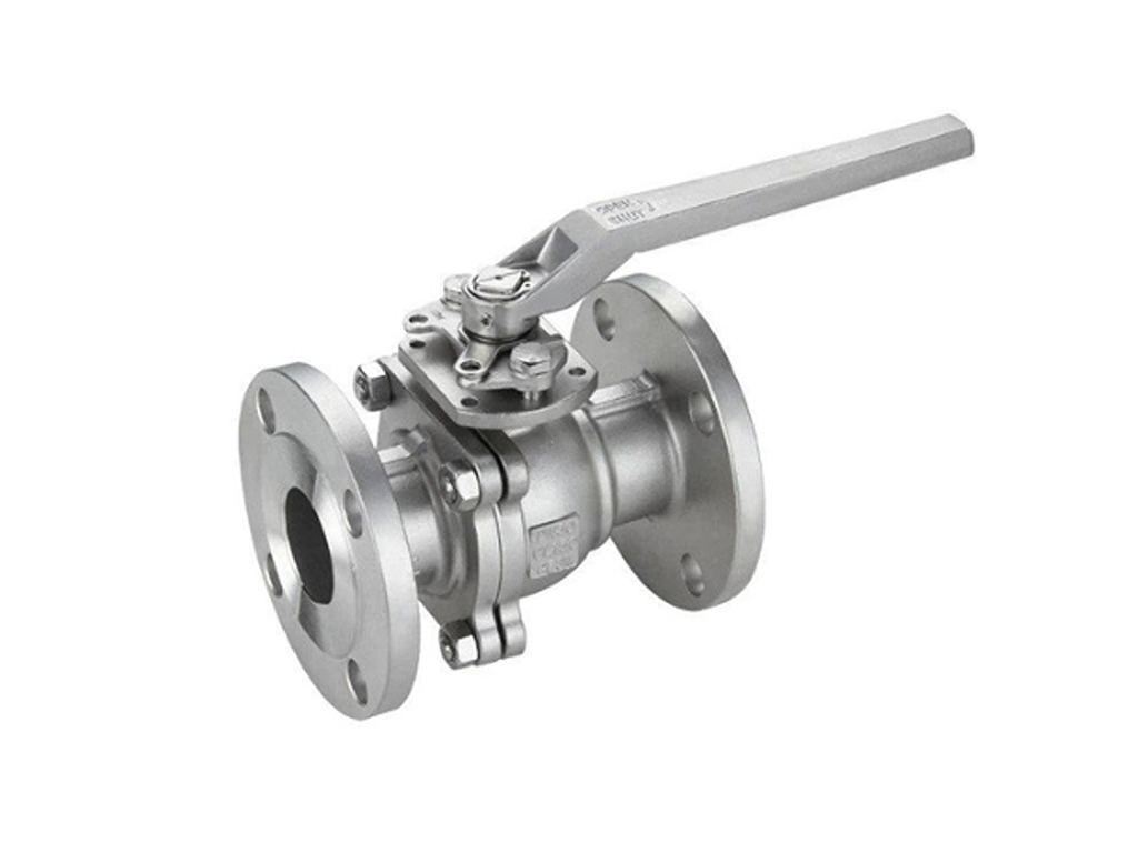
A ball valve is a quarter-turn shut-off valve: the closing element is a sphere with a cylindrical bore through its center. Rotate the sphere 90 degrees and the bore aligns with the pipe, and the valve is open. Rotate it back and the solid face of the sphere blocks the flow path, and the valve is closed. That is the entire operating principle in two sentences, and the reason the handle position is a reliable status indicator: handle parallel to the pipe means open, perpendicular means closed.
Four parts make this possible:
- Ball. The bored sphere that rotates inside the valve. Its bore is the flow passage.
- Stem. The shaft that connects the handle (or actuator) to the ball and transmits the rotation.
- Seats. Two rings, usually PTFE-based, that support the ball and form the actual sealing surfaces.
- Body. The pressure-containing housing with the inlet and outlet ports.
One clarification before we go deeper. It is a constant source of confusion in search results: a floating ball valve (covered in this article) is not the same thing as a ball float valve. The float valve is a liquid-level control device with a lever and a hollow float, a completely different product category. If you are here for the shut-off valve, you are in the right place.
The rest of this article answers the question most guides stop short of. Not just how the ball rotates, but why the valve seals, when it stops sealing, and which design you should be buying.
How a Ball Valve Actually Seals: The Seat, Not the Ball
Here is the mechanism that changes how you read ball valve failures: a ball valve seals because the fluid pressure pushes the ball against the downstream seat.
In a closed floating ball valve, the ball is not clamped in place; it is free to shift slightly in the flow direction. When the valve is closed and there is pressure on the upstream side, that pressure pushes the ball downstream, pressing it harder against the seat ring. The higher the differential pressure, the tighter the seal. Engineers call this pressure-energized sealing. Experienced process engineers describe it in exactly these terms: “the more dP, the harder the ball is pressed into the seat” (eng-tips forum, floating ball valves leaking at low pressure).
That mechanism has a direct consequence: at very low pressure, the seal gets weaker. If the differential pressure is near zero, nothing pushes the ball against the seat. The valve relies entirely on the interference fit the manufacturer built in at the factory: the seat ring is machined slightly smaller than the ball so it grips it. That factory preload is the only thing holding the seal at zero pressure, and it degrades with wear and time.
💡 The takeaway: ball valve sealing is pressure-dependent by design. “Leaks at low pressure” is not necessarily a defective valve; it may be the working principle itself reaching its boundary.
That last sentence matters more than it looks. It is the boundary anchor for everything that follows. If you maintain or buy valves for industrial systems, the details below determine whether your line weeps and when your seats need replacing. They also decide whether you should have specified a different valve design entirely. If you are just fixing a garden valve, the next three sections are still useful, but the industrial reader will live or die by them.
One more boundary worth naming now: a ball valve is an on/off device, not a flow control device. Partial opening makes the seat the throttle surface. Uneven wear, vibration, and premature seat failure follow.
Types of Ball Valves: Three Structural Layers, One Working Principle
Every ball valve type is the same working principle with a different structure, and structure is the fastest way to understand the principle. Three structural layers separate the types: how the ball is supported, how the ports and bore are shaped, and who turns the stem. A fourth dimension — body design — is a maintenance choice rather than a function choice. This section walks the full map, marking what is common and what is rare, so you can place any valve you meet.
Ball Support: Floating and Trunnion — the Two Most Common Designs
⭐ The two most common ball valve designs in industrial piping are floating and trunnion. The floating design is the mechanism from the previous section in its purest form: the ball is not anchored, and line pressure pushes it against the downstream seat. Simple, lightweight, economical. And sealing quality is directly tied to pressure. It is the design most manufacturers ship the most of.
The trunnion design anchors the ball with a fixed shaft (the trunnion) and spring-loaded seats, so the seal does not depend on pressure. It works just as well at 1 bar as at 100 bar, at the cost of complexity and price. Where is the boundary between them? Working engineers have developed rules of thumb, and they are worth writing down because almost nobody publishes them. From a veteran process engineer on eng-tips, the experienced defaults are: trunnion above about 12" in Class 150 and 8" in Class 300, and trunnion down to 4" for low-pressure gas service (near-vacuum to about 10 psig). His reason: “because I’ve had problems with floaters being able to shift the ball enough to seal at very low dP after they’ve been in service a couple of years” (eng-tips forum, 150# ball valves — trunnion vs. floating). These are practitioner conventions, not a standard. Different companies draw the line differently, but they exist because the physics is the same everywhere.
Floating vs. Trunnion Ball Valve: Which Design for Your Scenario
| Application Scenario | Floating Ball Valve | Trunnion Ball Valve | Boundary |
|---|---|---|---|
| Standard shut-off at normal pressures | ✅ typical choice — simple, economical | Overkill — extra cost without benefit | Up to ~12" Class 150 per practitioner rules of thumb |
| Low-pressure service (near-vacuum to ~10 psig gas) | ⚠️ risk — seal depends on pressure | ✅ correct choice — spring-loaded seats seal at any dP | Engineers specify trunnion down to 4" here |
| Large bore (≥12" Class 150 / ≥8" Class 300) | ⚠️ heavy ball + pressure loads strain the seats | ✅ standard choice | Switch point per common engineering practice |
| Frequent cycling / high cycle counts | Seat wear shortens preload life | Spring-loaded seats compensate wear | Trunnion preferred |
| Double block & bleed or ESD service | ❌ not acceptable — no guaranteed seal | ✅ required regardless of size | Design standard practice |
| Dirty / particle-laden media | Particles can embed in seats; ball shifts | Sealed cavity designs available | Trunnion with sealed trunnion bearings |
| Budget-constrained project | ✅ lowest cost | Highest cost of the two | Cost difference roughly 2–3x |
The decision table above is the practical tool: read down the rows, and the design chooses itself. One data point explains why the choice matters financially. In a real failure case documented on eng-tips, a facility selected floating valves for a low-pressure application. The valves wept at low differential pressure, and the remedy cost roughly three times the original valve price. The fix was replacing them with trunnion designs (eng-tips forum, floating ball valves leaking at low pressure). The working principle did not change between purchase and failure; the selection did.
the field cost of replacing floating ball valves with trunnion designs, versus selecting right the first time
Ports and Bore: 2-Way, 3-Way, and V-Port
The second structural layer is the ports and the bore, and here the bore shape is the function. A standard 2-way valve carries a straight cylindrical bore: fully aligned means open, fully turned means closed. Change the bore and the same quarter-turn gains new jobs.
A 3-way valve adds a third port and an L-shaped or T-shaped bore. The L-port connects two of the three ports at a time, which is the diverting job — alternating between two storage tanks, for example. At every rotation angle, some pair of ports is connected. “off” is not one of the options. If your process needs positive isolation, a 3-way valve cannot provide it alone; you need a separate shut-off valve or a design that includes a closed position. The T-port connects all three at once, which is what mixing two streams or distributing one requires. The selection rule is short: switching between paths, choose L; combining or splitting streams, choose T. Install the wrong bore shape and the function simply does not exist.
Rotation keeps two ports connected at every angle — if the process demands positive isolation, plan a separate shut-off valve.
Two more variants fill out the map. The V-port ball carries a V-shaped bore that passes flow progressively as the valve opens — the rare case where a ball valve can throttle. And in body design — one-piece, split (two- or three-piece), top-entry, and welded (Valtorc International, ball valve body types) — the difference is maintenance, not function: split bodies open for seat service, top-entry valves service from above without leaving the line, and welded bodies trade serviceability for fewer leak paths.
Operation: Manual vs. Actuated — the Layer Where the Industry Is Moving
The third structural layer is who turns the stem. A manual valve needs nothing but a person at the handle — right for valves within arm’s reach that cycle a few times a day, and the honest default for budget-conscious projects. Most ball valves still ship with a lever.
The limit of the handle is distance and response. When the valve sits in a tank farm, inside a machine skid, or in a line that must respond faster than a person can walk there, an actuator puts the same quarter-turn behind a control signal. The industry is moving toward actuation as the default, not the exception. Three forces push that direction. First, control architectures (DCS and PLC systems) assume every final element can be commanded remotely. Second, maintenance crews are shrinking while plant complexity grows, so valves that operate and report themselves save labor that no longer exists to spend on walking routes. Third, the AI wave in industrial operations — predictive maintenance, automated process control, automated response sequences — assumes every valve can be commanded by software. A manual valve is invisible to that trend.
Once automation enters the picture, the question stops being whether and becomes which driver — compressed air or electric power.
Pneumatic vs. Electric Actuators: Choosing the Driver
Both actuator families do the same job: rotate the stem 90 degrees on command. They differ in how they generate that rotation, and the difference maps cleanly onto plant infrastructure.
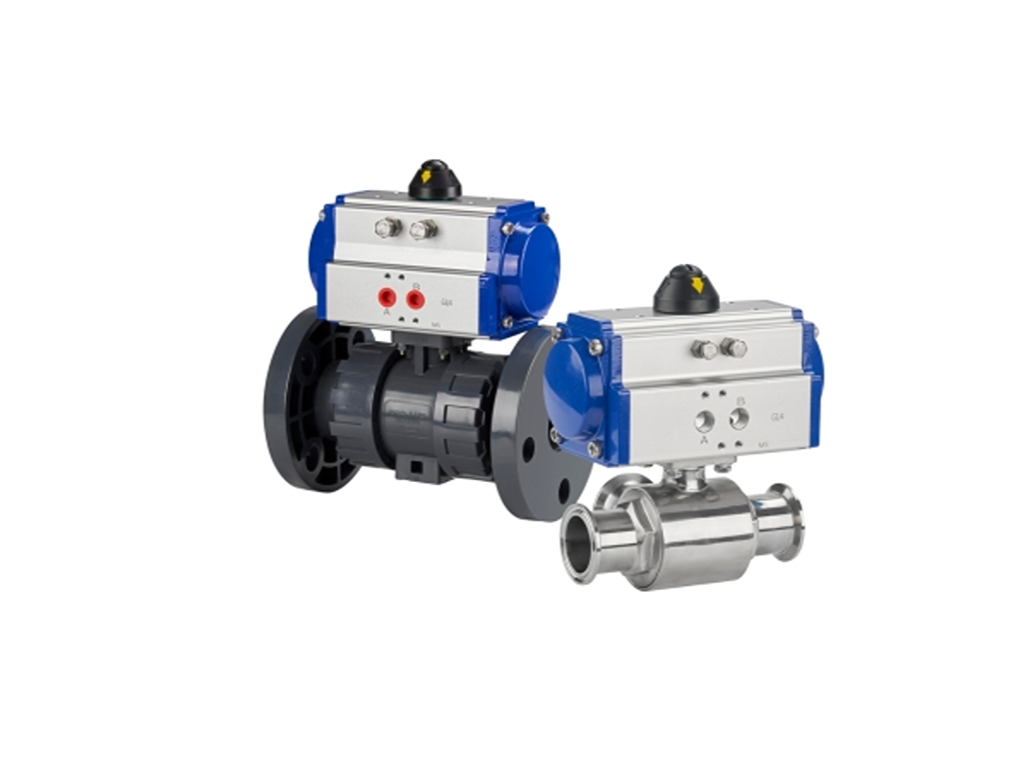
Pneumatic Actuators: The Rack-and-Pinion Motion Chain
The most common pneumatic mechanism is the rack-and-pinion drive. The full motion chain has five links:
- A controller sends an electrical signal to a solenoid valve, which switches the air path.
- Compressed air enters one chamber of the actuator cylinder.
- The air pressure drives the piston, producing linear motion.
- The piston carries a rack (a linear gear) that meshes with a pinion (a circular gear). This classic rack-and-pinion mechanism converts the linear stroke into rotation.
- The pinion turns the valve stem 90 degrees, rotating the ball to open or close.
Reversing the air supply reverses the rotation. The whole cycle is fast: pneumatic actuators complete the quarter turn in under a second with typical plant air around 4–8 bar.
Pneumatic actuators come in two configurations, and the choice is a safety decision, not a performance detail:
- Single-acting (spring return): compressed air pushes the piston one way; a spring pushes it back when the air is vented. If the air supply is lost, the valve automatically returns to its spring-set position: normally closed or normally open, whichever the spring is set for. This is the built-in fail-safe. Loss of air equals a known, safe valve position.
- Double-acting: air pressure drives the piston both ways. One port opens, the other closes. No spring, so on air loss the valve stays where it was. Fail-safe requires external accessories. Double-acting units are cheaper and stronger, which is why they dominate routine automation.
The practical question is always: what must this valve do if the plant loses air? For emergency isolation, critical cooling, or vent lines, spring return is the standard answer. For ordinary on/off automation, double-acting is fine.
Electric Actuators: Motor, Gears, and Precise Positioning
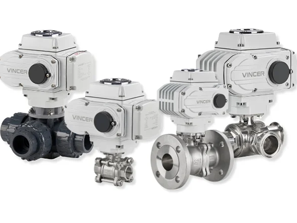
An electric actuator drives the same 90-degree rotation with a different engine. An electric motor turns a gear train that rotates the valve stem. Where a pneumatic unit needs compressed air, an electric unit needs only a power supply. That makes it the default in plants without air infrastructure, and in clean, energy-conscious processes.
The motor-and-gear assembly also defines what electric actuation is good at. It is slower than pneumatic: typically 20 to 100 seconds for the full quarter turn, against under a second for air. But it can stop the ball anywhere between 0 and 90 degrees with repeatable precision. Modulating flow, holding a setpoint, or tracking a control signal all become possible, which is why electric actuators power the modulating ball valves used in blending and temperature control.
The choice is a site question, not a valve question. Pneumatic wins where air is already on the plant floor, where cycling is fast, and where fail-safe must survive a power loss through spring return. The cost is a compressor and air treatment. Electric wins where precision, quiet operation, and energy efficiency matter, and where no air system exists. A supplier that builds both lines can answer that question without steering you. VINCER’s range runs from rack-and-pinion pneumatic actuators at 8 to 4,678 N·m of torque, with ATS spring-return units from 5.7 to 2,792 N·m and sub-second response (pneumatic actuated valve). On the electric side, quarter-turn units go up to 4,000 N·m with modulating control.
Automated ball valves also standardize the mechanical interface. ISO 5211 defines the mounting flange dimensions and torque classes for attaching part-turn actuators to industrial valves (ISO 5211:2017 — Part-turn actuator attachments). Because of it, valves and actuators from different manufacturers can be matched on the same flange pattern. That also means the actuator’s torque rating must exceed the valve’s breakaway torque, a number the valve manufacturer must state.
If you are matching an actuator to a ball valve, send your valve size and service conditions — VINCER’s engineers will confirm the torque and interface for you.
Ask a valve engineerWhy Ball Valves Fail: Field Symptoms and Root Causes
Every ball valve failure is either a sealing failure or a motion failure, and the working principle we covered determines the root causes. Here is the field diagnostic table, symptom first, the way you actually meet these problems:
| Symptom | Root cause | Fix |
|---|---|---|
| Dripping at the handle/stem | Stem packing (the seal around the stem) worn | Replace or tighten the packing gland — the most common domestic failure |
| Weeps at low pressure when closed | Pressure-energized sealing needs differential pressure; factory preload is exhausted | Check the actual dP; consider a trunnion design or upgraded seat material |
| Weeps after years of high-pressure service | Seat cold flow: PTFE seats permanently deform under sustained high pressure — “virgin TFE has low memory, so once it is exposed to high-pressure shutoff for a while, the downstream seat is permanently distorted and the preload is gone” (eng-tips forum) | Specify reinforced seats (glass-filled PTFE / RPTFE) for pressure-cycled service |
| Hard to turn / sticks | Debris or scale in the ball cavity, or seat material swelled by the media | Flush the line; check media compatibility against the seat material |
| Leak at the body/end connections | Installation torque or gasket issues | Re-torque to spec; replace gasket |
The diagnostic sequence matters as much as the table: first locate the leak (stem, seat, or body), then apply the fix. A seat leak fixed with packing will leak again; a stem leak “fixed” by replacing the whole valve wastes money. And note the pattern running through the table: several of these are design-and-application problems, not product-quality problems. That is exactly what makes them so expensive when misdiagnosed.
Design-and-application problems, not product-quality problems.
The pattern running through the failure table above
What the Working Principle Means for the People Buying Valves
The failure table above has a business punchline that the engineers in it discovered the hard way. A low-pressure weeping valve gets blamed on the supplier, even when the working principle is doing exactly what it does.
Here is the pattern, from real field experience on eng-tips. A facility installs floating ball valves in low-pressure service, the valves weep at near-zero differential pressure, and the team’s first move is to change supplier. The new floating valves weep too, because the mechanism is the same. The actual fix was a different design (trunnion, with spring-loaded seats), and it cost roughly three times the original purchase (eng-tips forum). Same story plays out with seat material: PTFE cold flow after years of high-pressure shutoff is a material property, not a manufacturing defect. A reinforced seat or a different material fixes what a brand change never will.
That is the engineering picture. For the distributors and wholesalers who stock and sell these valves for a living, the same structure reads differently. It reads as margin, inventory, and timing — and the structure of the product is also the structure of the business. Four conclusions follow directly from the facts above.
Volume lives in floating ball valves; profit lives in actuated assemblies. A floating ball valve is close to a commodity: the materials, machining, and seats are transparent in the catalog, and so is the price. It is also the type most manufacturers ship the most of — which is why it moves fast and earns thin margins, with buyers comparing quotes on price. Add an actuator and the picture flips. The assembly carries engineering value — torque matching against breakaway, ISO 5211 interface selection, fail-safe logic, control-signal integration — that a catalog price cannot commoditize. It also needs selection support, which is exactly the service role a distributor earns margin for. The inventory conclusion is direct: stock floating ball valves for turnover, and build the actuated line for margin.
Timing is the second conclusion, and it is the reason to act now. The automation trend from the types section is not a prediction — it is measurable. Electric actuators’ share of the control valve market is projected to rise from roughly 19% in 2025 toward 30% by 2035 (Market Research Future, control valve market report, 2025). Demand for actuated assemblies grows while the catalog price of bare valves stays flat. A distributor who waits until customers ask for actuators has already sent those customers to a competitor; one who stocks the actuated line now is positioned before the question arrives.
The “quality problem” returns are often structure problems — and that knowledge is a distributor’s edge. When a customer returns a weeping valve as defective, the field table earlier in this article usually tells the real story: pressure-energized sealing at low dP, or PTFE cold flow after high-pressure service. A distributor who can diagnose that on the spot converts a refund into a solution (reinforced seats, or a trunnion upgrade), keeps the account, and gains a reputation no price comparison can match.
That is why a supplier’s product-line breadth is a selection tool, not a marketing claim. Building this inventory structure takes one vendor that covers both structural layers — ball valves across floating, trunnion, and 3-way designs, plus pneumatic and electric actuators matched as assemblies. A manufacturer like VINCER carries a floating and trunnion ball valve series spanning 3/8" to 12", rated across PN, Class, and JIS pressure systems. V-port and 3-way variants cover the cases where a standard two-way valve is the wrong answer (ball valve series). When the application calls for automation, the same supplier can pair the valve with a pneumatic or electric actuator as one assembly (pneumatic actuated valve). Torque matching, response time, and the ISO 5211 interface are then resolved before the unit reaches your warehouse. The ones that can show you the whole spectrum are the ones who let you run a one-order business instead of a patchwork of suppliers.
None of this makes the ball valve any more complicated than the quarter-turn it appears to be. It makes it predictable: the mechanism explains the failure, the failure explains the selection, and the selection explains the cost. That chain — mechanism, structure, margin, timing — is the entire working principle. And now it is yours to use.
Send your size range, pressure class, media, and actuation needs. Simple specs get a quote within 24 hours.
Request a QuoteReferences
- eng-tips forum. “Floating ball valves leaking at low pressure.” 2009.
- eng-tips forum. “150# ball valves — trunnion vs floating.” 2010.
- ISO. “ISO 5211:2017 — Industrial valves. Part-turn actuator attachments.”
- Market Research Future. “Control Valve Market Size, Share & Growth Report.” 2025.
- VINCER Valve. “Ball Valve Series.”
- VINCER Valve. “Pneumatic Actuated Valve.”
- VINCER Valve. Homepage.
- Valtorc International. “The 4 Types of Ball Valves — Single Body, Split Body, Top Entry and Welded.” 2013.