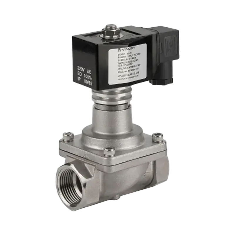
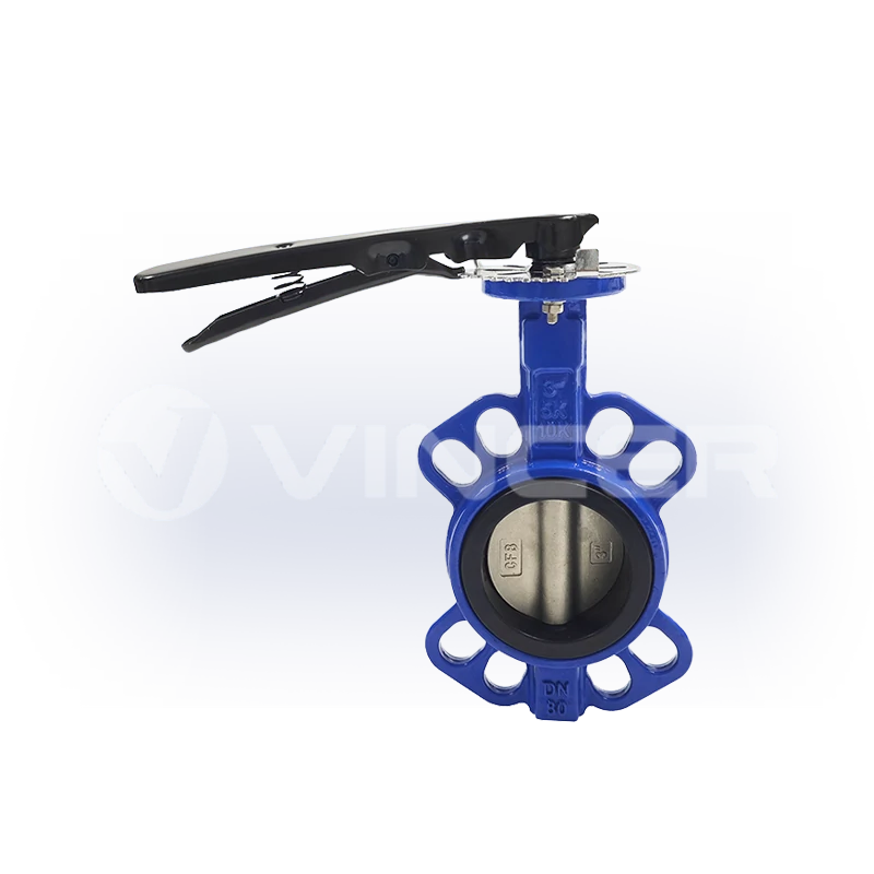
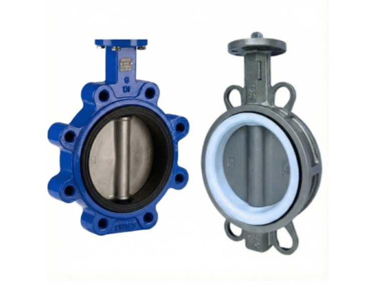
اسأل مهندس أنابيب عن ماهية الصمام الكروي، فسيقول لك نفس ما يقوله صاحب المنزل الذي يقوم بأعمال الصيانة بنفسه، لكن بكلمات أقل. إنها كرة دوارة بها فتحة، تعمل على فتح وإغلاق التدفق بربع دورة. هذا الوصف صحيح، لكنه يخفي كل ما هو مهم تقريبًا. فالكرة لا تعمل بمفردها على إحكام الإغلاق، بل المقعد هو الذي يقوم بذلك، وكذلك الضغط. وبمجرد أن تفهم ذلك، يصبح كل عطل في الصمام الكروي الذي قد تراه قابلاً للتنبؤ: التسرب الناتج عن انخفاض الضغط، وتآكل المقعد بعد سنوات من الاستخدام، والمشغلات التي “تفقد قبضتها”.
تستعرض هذه المقالة مبدأ العمل بالترتيب الذي يواجهه المشتري فعليًّا: الأجزاء، وآلية الإحكام الفعلية، والخريطة الكاملة لأنواع الصمامات الكروية — بدءًا من التصميمين الأكثر شيوعًا وصولاً إلى الطبقات الهيكلية الكامنة وراءهما. ثم نقارن بين التشغيل اليدوي والتشغيل الآلي، والمشغلات الهوائية والكهربائية التي تقف وراء الأتمتة، وأنماط الأعطال التي تنجم مباشرةً عن القوانين الفيزيائية. ونسلط الضوء خلال ذلك على الشروط الحدية التي تتجاهلها معظم الأدلة الإرشادية. فهذه الشروط هي التي تحدد قرارات الشراء.
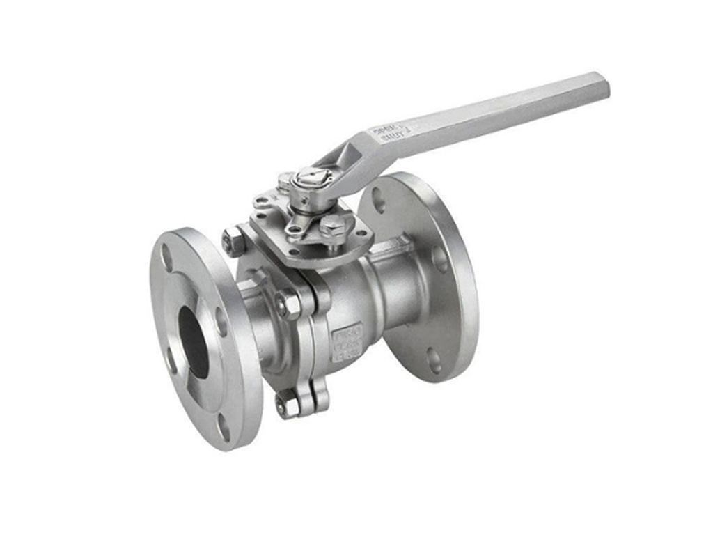
ما هو الصمام الكروي؟ الأجزاء الأربعة التي تعتمد عليها آلية الدوران ربع الدورة
الصمام الكروي هو صمام إغلاق يعمل بربع دورة: حيث يتكون عنصر الإغلاق من كرة بها فتحة أسطوانية تمر عبر مركزها. عند تدوير الكرة 90 درجة، تتوازى الفتحة مع الأنبوب، فيصبح الصمام مفتوحًا. أدره في الاتجاه المعاكس، فيقوم السطح الصلب للكرة بسد مسار التدفق، فيصبح الصمام مغلقًا. هذا هو مبدأ التشغيل بأكمله في جملتين، وهو السبب في أن وضع المقبض يُعد مؤشرًا موثوقًا للحالة: فالمقبض الموازي للأنبوب يعني أن الصمام مفتوح، أما المقبض العمودي عليه فيعني أنه مغلق.
هناك أربعة عناصر تجعل ذلك ممكنًا:
- الكرة. الكرة المجوفة التي تدور داخل الصمام. ويشكل تجويفها ممر التدفق.
- الساق. العمود الذي يربط المقبض (أو المشغل) بالكرة وينقل الدوران.
- المقاعد. حلقتان، عادةً ما تكونان مصنوعتين من مادة PTFE، تدعمان الكرة وتشكلان أسطح الإحكام الفعلية.
- النص الرئيسي. العلبة المضغوطة المزودة بفتحتي المدخل والمخرج.
توضيح واحد قبل أن نتعمق أكثر. إنه مصدر دائم للالتباس في نتائج البحث: أ صمام كروي عائم (الذي تم تناوله في هذا المقال) ليس هو نفسه صمام العوامة الكروية. صمام العوامة هو جهاز للتحكم في مستوى السائل مزود بذراع وعوامة مجوفة، وهو ينتمي إلى فئة منتجات مختلفة تمامًا. إذا كنت تبحث عن صمام الإغلاق، فأنت في المكان الصحيح.
تتناول بقية هذه المقالة السؤال الذي تتجنب معظم الأدلة الخوض فيه. ليس فقط كيف تدور الكرة, ، لكن لماذا تعمل الصمامات على منع التسرب، ومتى تتوقف عن ذلك، وما هو التصميم الذي ينبغي عليك شراؤه.
كيف يعمل الصمام الكروي فعليًّا على إحكام الإغلاق: المقعد، وليس الكرة
إليك الآلية التي تغير طريقة تحليل أعطال الصمامات الكروية: يتم إحكام إغلاق الصمام الكروي لأن ضغط السائل يدفع الكرة نحو المقعد الموجود في اتجاه تدفق السائل.
في الصمام الكروي العائم المغلق، لا يتم تثبيت الكرة في مكانها؛ بل لها حرية التحرك قليلاً في اتجاه التدفق. وعندما يكون الصمام مغلقاً ويوجد ضغط على الجانب العلوي من مجرى التدفق، فإن هذا الضغط يدفع الكرة باتجاه مجرى التدفق، مما يضغطها بقوة أكبر على حلقة المقعد. وكلما زاد الفرق في الضغط، زادت إحكام الإغلاق. ويطلق المهندسون على هذا إحكام الإغلاق المعزز بالضغط. ويصفه مهندسو العمليات ذوو الخبرة بهذه العبارة بالضبط: “كلما زاد dP، زادت قوة ضغط الكرة على المقعد” (منتدى eng-tips، تسرب الصمامات الكروية العائمة عند الضغط المنخفض).
ولهذه الآلية نتيجة مباشرة وهي: عند الضغط المنخفض جدًّا، تقل قوة المانع للتسرب. إذا كان الفرق في الضغط قريبًا من الصفر، فلا يوجد ما يدفع الكرة نحو المقعد. ويعتمد الصمام كليًّا على التثبيت بالضغط الذي صممه المصنع في المصنع: حيث يتم تصنيع حلقة المقعد بحجم أصغر قليلاً من الكرة بحيث تثبت عليها. وهذا التحميل المسبق من المصنع هو العامل الوحيد الذي يحافظ على السدادة عند ضغط صفر، وهو يتدهور مع التآكل ومرور الوقت.
💡 النقطة الأساسية: يعتمد إحكام إغلاق الصمام الكروي، بحكم تصميمه، على الضغط. ولا تعني “التسربات عند الضغط المنخفض” بالضرورة أن الصمام معيب؛ بل قد يكون ذلك بسبب وصول مبدأ التشغيل نفسه إلى حدوده القصوى.
تلك الجملة الأخيرة أكثر أهمية مما تبدو عليه. فهي بمثابة نقطة مرجعية أساسية لكل ما يليها. إذا كنت تقوم بصيانة أو شراء الصمامات للأنظمة الصناعية، فإن التفاصيل الواردة أدناه تحدد ما إذا كان خط الأنابيب الخاص بك يتسرب ومتى تحتاج مقاعد الصمامات إلى الاستبدال. كما أنها تحدد ما إذا كان ينبغي عليك تحديد تصميم مختلف تمامًا للصمام. وإذا كنت تقوم فقط بإصلاح صمام حديقة، فإن الأقسام الثلاثة التالية تظل مفيدة، لكن القارئ المتخصص في المجال الصناعي سيعتمد عليها بشكل حاسم.
هناك حد آخر يستحق الذكر الآن: الصمام الكروي هو جهاز تشغيل/إيقاف، وليس جهازًا للتحكم في التدفق. يؤدي الفتح الجزئي إلى تحول المقعد إلى سطح خانق. ويترتب على ذلك تآكل غير متساوٍ واهتزازات وفشل مبكر في المقعد.
أنواع الصمامات الكروية: ثلاث طبقات هيكلية، مبدأ عمل واحد
تتبع جميع أنواع الصمامات الكروية نفس مبدأ التشغيل، لكن تختلف في هيكلها، ويُعد الهيكل أسرع طريقة لفهم هذا المبدأ. وهناك ثلاث طبقات هيكلية تميز بين الأنواع المختلفة: طريقة تثبيت الكرة، وشكل المنافذ والتجويف، والجهة المسؤولة عن تدوير العمود. أما البعد الرابع — تصميم الجسم — فهو خيار يتعلق بالصيانة وليس بالوظيفة. يستعرض هذا القسم الخريطة الكاملة، موضحًا ما هو شائع وما هو نادر، حتى تتمكن من تحديد أي صمام تصادفه.
دعامات الكرات: العائمة والمحورية — التصميمان الأكثر شيوعًا
⭐ أكثر تصميمين شيوعًا للصمامات الكروية في الأنابيب الصناعية هما التصميم العائم والتصميم المحوري. يُعد التصميم العائم هو الآلية التي تم تناولها في القسم السابق في أبسط صورها: فالكرة غير مثبتة، ويقوم ضغط الخط بدفعها نحو المقعد الموجود في اتجاه مجرى التيار. إنه تصميم بسيط وخفيف الوزن واقتصادي. وترتبط جودة الإحكام ارتباطًا مباشرًا بالضغط. وهو التصميم الذي ينتجه معظم المصنعين بأكبر كميات.
يعتمد تصميم المحور الدوار على تثبيت الكرة بواسطة عمود ثابت (المحور الدوار) ومقاعد مزودة بنوابض، بحيث لا يعتمد الإغلاق على الضغط. وهو يعمل بنفس الكفاءة عند ضغط 1 بار كما عند 100 بار، على حساب التعقيد والسعر. فأين يقع الحد الفاصل بينهما؟ لقد طور المهندسون الممارسون قواعد عامة، وتستحق هذه القواعد أن تُدوَّن لأن لا أحد تقريبًا ينشرها. وفقًا لمهندس عمليات مخضرم على موقع eng-tips، فإن القيم الافتراضية المستندة إلى الخبرة هي: أن يكون عمود الدوران أعلى من حوالي 12 بوصة من الفئة 150 و 8 بوصات من الفئة 300, ، ومحور الدوران وصولاً إلى 4 بوصات لخطوط الغاز ذات الضغط المنخفض (من حالة شبه تفريغ إلى حوالي 10 رطل لكل بوصة مربعة). والسبب الذي ذكره هو: “لأنني واجهت مشاكل في قدرة العوامات على تحريك الكرة بما يكفي لإحكام الإغلاق عند فرق ضغط منخفض جدًّا بعد مرور بضع سنوات على تشغيلها” (منتدى eng-tips، الصمامات الكروية 150# — النوع الثابت مقابل النوع العائم). These are practitioner conventions, not a standard. Different companies draw the line differently, but they exist because the physics is the same everywhere.
Floating vs. Trunnion Ball Valve: Which Design for Your Scenario
| Application Scenario | Floating Ball Valve | Trunnion Ball Valve | Boundary |
|---|---|---|---|
| Standard shut-off at normal pressures | ✅ typical choice — simple, economical | Overkill — extra cost without benefit | Up to ~12" Class 150 per practitioner rules of thumb |
| Low-pressure service (near-vacuum to ~10 psig gas) | ⚠️ risk — seal depends on pressure | ✅ correct choice — spring-loaded seats seal at any dP | Engineers specify trunnion down to 4" here |
| Large bore (≥12" Class 150 / ≥8" Class 300) | ⚠️ heavy ball + pressure loads strain the seats | ✅ standard choice | Switch point per common engineering practice |
| Frequent cycling / high cycle counts | Seat wear shortens preload life | Spring-loaded seats compensate wear | Trunnion preferred |
| Double block & bleed or ESD service | ❌ not acceptable — no guaranteed seal | ✅ required regardless of size | Design standard practice |
| Dirty / particle-laden media | Particles can embed in seats; ball shifts | Sealed cavity designs available | Trunnion with sealed trunnion bearings |
| Budget-constrained project | ✅ lowest cost | Highest cost of the two | Cost difference roughly 2–3x |
The decision table above is the practical tool: read down the rows, and the design chooses itself. One data point explains why the choice matters financially. In a real failure case documented on eng-tips, a facility selected floating valves for a low-pressure application. The valves wept at low differential pressure, and the remedy cost roughly three times the original valve price. The fix was replacing them with trunnion designs (منتدى eng-tips، تسرب الصمامات الكروية العائمة عند الضغط المنخفض). The working principle did not change between purchase and failure; the selection did.
the field cost of replacing floating ball valves with trunnion designs, versus selecting right the first time
Ports and Bore: 2-Way, 3-Way, and V-Port
The second structural layer is the ports and the bore, and here the bore shape is the function. A standard 2-way valve carries a straight cylindrical bore: fully aligned means open, fully turned means closed. Change the bore and the same quarter-turn gains new jobs.
A 3-way valve adds a third port and an L-shaped or T-shaped bore. The L-port connects two of the three ports at a time, which is the diverting job — alternating between two storage tanks, for example. At every rotation angle, some pair of ports is connected. “off” is not one of the options. If your process needs positive isolation, a 3-way valve cannot provide it alone; you need a separate shut-off valve or a design that includes a closed position. The منفذ T connects all three at once, which is what mixing two streams or distributing one requires. The selection rule is short: switching between paths, choose L; combining or splitting streams, choose T. Install the wrong bore shape and the function simply does not exist.
Rotation keeps two ports connected at every angle — if the process demands positive isolation, plan a separate shut-off valve.
Two more variants fill out the map. The منفذ V-port ball carries a V-shaped bore that passes flow progressively as the valve opens — the rare case where a ball valve can throttle. And in body design — one-piece, split (two- or three-piece), top-entry, and welded (Valtorc International, ball valve body types) — the difference is maintenance, not function: split bodies open for seat service, top-entry valves service from above without leaving the line, and welded bodies trade serviceability for fewer leak paths.
Operation: Manual vs. Actuated — the Layer Where the Industry Is Moving
The third structural layer is who turns the stem. A manual valve needs nothing but a person at the handle — right for valves within arm’s reach that cycle a few times a day, and the honest default for budget-conscious projects. Most ball valves still ship with a lever.
The limit of the handle is distance and response. When the valve sits in a tank farm, inside a machine skid, or in a line that must respond faster than a person can walk there, an actuator puts the same quarter-turn behind a control signal. The industry is moving toward actuation as the default, not the exception. Three forces push that direction. First, control architectures (DCS and PLC systems) assume every final element can be commanded remotely. Second, maintenance crews are shrinking while plant complexity grows, so valves that operate and report themselves save labor that no longer exists to spend on walking routes. Third, the AI wave in industrial operations — predictive maintenance, automated process control, automated response sequences — assumes every valve can be commanded by software. A manual valve is invisible to that trend.
Once automation enters the picture, the question stops being whether and becomes which driver — compressed air or electric power.
Pneumatic vs. Electric Actuators: Choosing the Driver
Both actuator families do the same job: rotate the stem 90 degrees on command. They differ in how they generate that rotation, and the difference maps cleanly onto plant infrastructure.
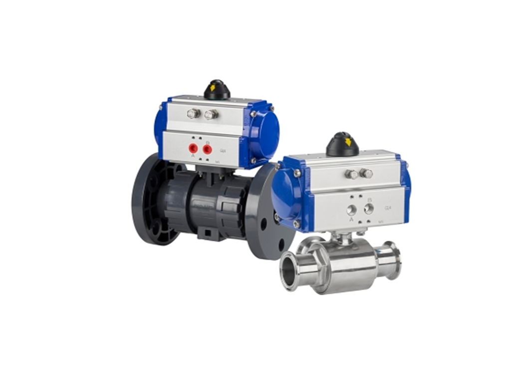
Pneumatic Actuators: The Rack-and-Pinion Motion Chain
The most common pneumatic mechanism is the rack-and-pinion drive. The full motion chain has five links:
- A controller sends an electrical signal to a صمام الملف اللولبي, which switches the air path.
- Compressed air enters one chamber of the actuator cylinder.
- The air pressure drives the piston, producing linear motion.
- The piston carries a rack (a linear gear) that meshes with a pinion (a circular gear). This classic rack-and-pinion mechanism converts the linear stroke into rotation.
- The pinion turns the valve stem 90 degrees, rotating the ball to open or close.
Reversing the air supply reverses the rotation. The whole cycle is fast: pneumatic actuators complete the quarter turn in under a second with typical plant air around 4–8 bar.
Pneumatic actuators come in two configurations, and the choice is a safety decision, not a performance detail:
- Single-acting (spring return): compressed air pushes the piston one way; a spring pushes it back when the air is vented. If the air supply is lost, the valve automatically returns to its spring-set position: normally closed or normally open, whichever the spring is set for. This is the built-in fail-safe. Loss of air equals a known, safe valve position.
- Double-acting: air pressure drives the piston both ways. One port opens, the other closes. No spring, so on air loss the valve stays where it was. Fail-safe requires external accessories. Double-acting units are cheaper and stronger, which is why they dominate routine automation.
The practical question is always: what must this valve do if the plant loses air? For emergency isolation, critical cooling, or vent lines, spring return is the standard answer. For ordinary on/off automation, double-acting is fine.
Electric Actuators: Motor, Gears, and Precise Positioning
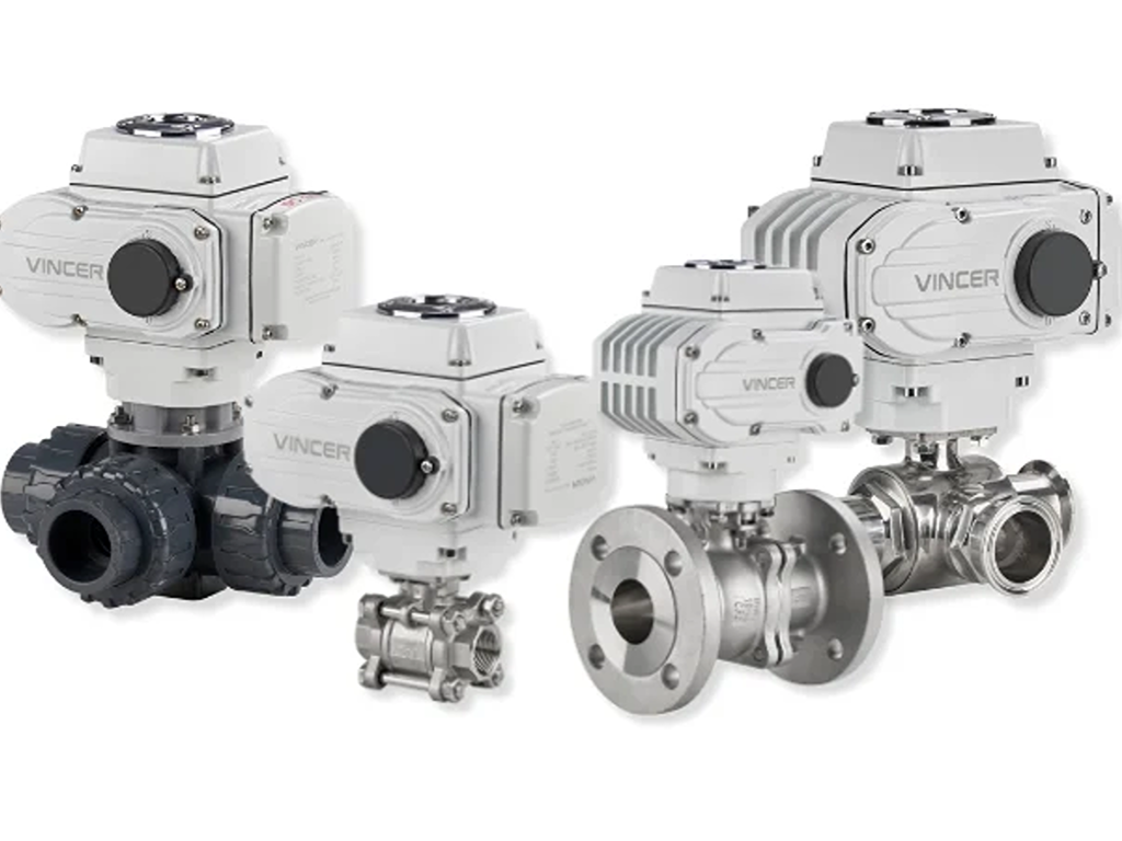
An electric actuator drives the same 90-degree rotation with a different engine. An electric motor turns a gear train that rotates the valve stem. Where a pneumatic unit needs compressed air, an electric unit needs only a power supply. That makes it the default in plants without air infrastructure, and in clean, energy-conscious processes.
The motor-and-gear assembly also defines what electric actuation is good at. It is slower than pneumatic: typically 20 to 100 seconds for the full quarter turn, against under a second for air. But it can stop the ball anywhere between 0 and 90 degrees with repeatable precision. Modulating flow, holding a setpoint, or tracking a control signal all become possible, which is why electric actuators power the modulating ball valves used in blending and temperature control.
The choice is a site question, not a valve question. Pneumatic wins where air is already on the plant floor, where cycling is fast, and where fail-safe must survive a power loss through spring return. The cost is a compressor and air treatment. Electric wins where precision, quiet operation, and energy efficiency matter, and where no air system exists. A supplier that builds both lines can answer that question without steering you. VINCER’s range runs from rack-and-pinion pneumatic actuators at 8 to 4,678 N·m of torque, with ATS spring-return units from 5.7 to 2,792 N·m and sub-second response (pneumatic actuated valve). On the electric side, quarter-turn units go up to 4,000 N·m with modulating control.
Automated ball valves also standardize the mechanical interface. ISO 5211 defines the mounting flange dimensions and torque classes for attaching part-turn actuators to industrial valves (ISO 5211:2017 — Part-turn actuator attachments). Because of it, valves and actuators from different manufacturers can be matched on the same flange pattern. That also means the actuator’s torque rating must exceed the valve’s breakaway torque, a number the valve manufacturer must state.
If you are matching an actuator to a ball valve, send your valve size and service conditions — VINCER’s engineers will confirm the torque and interface for you.
Ask a valve engineerWhy Ball Valves Fail: Field Symptoms and Root Causes
Every ball valve failure is either a sealing failure or a motion failure, and the working principle we covered determines the root causes. Here is the field diagnostic table, symptom first, the way you actually meet these problems:
| Symptom | Root cause | Fix |
|---|---|---|
| Dripping at the handle/stem | Stem packing (the seal around the stem) worn | Replace or tighten the packing gland — the most common domestic failure |
| Weeps at low pressure when closed | Pressure-energized sealing needs differential pressure; factory preload is exhausted | Check the actual dP; consider a trunnion design or upgraded seat material |
| Weeps after years of high-pressure service | Seat cold flow: PTFE seats permanently deform under sustained high pressure — “virgin TFE has low memory, so once it is exposed to high-pressure shutoff for a while, the downstream seat is permanently distorted and the preload is gone” (eng-tips forum) | Specify reinforced seats (glass-filled PTFE / RPTFE) for pressure-cycled service |
| Hard to turn / sticks | Debris or scale in the ball cavity, or seat material swelled by the media | Flush the line; check media compatibility against the seat material |
| Leak at the body/end connections | Installation torque or gasket issues | Re-torque to spec; replace gasket |
The diagnostic sequence matters as much as the table: first locate the leak (stem, seat, or body), then apply the fix. A seat leak fixed with packing will leak again; a stem leak “fixed” by replacing the whole valve wastes money. And note the pattern running through the table: several of these are design-and-application problems, not product-quality problems. That is exactly what makes them so expensive when misdiagnosed.
Design-and-application problems, not product-quality problems.
The pattern running through the failure table above
What the Working Principle Means for the People Buying Valves
The failure table above has a business punchline that the engineers in it discovered the hard way. A low-pressure weeping valve gets blamed on the supplier, even when the working principle is doing exactly what it does.
Here is the pattern, from real field experience on eng-tips. A facility installs floating ball valves in low-pressure service, the valves weep at near-zero differential pressure, and the team’s first move is to change supplier. The new floating valves weep too, because the mechanism is the same. The actual fix was a different design (trunnion, with spring-loaded seats), and it cost roughly three times the original purchase (eng-tips forum). Same story plays out with seat material: PTFE cold flow after years of high-pressure shutoff is a material property, not a manufacturing defect. A reinforced seat or a different material fixes what a brand change never will.
That is the engineering picture. For the distributors and wholesalers who stock and sell these valves for a living, the same structure reads differently. It reads as margin, inventory, and timing — and the structure of the product is also the structure of the business. Four conclusions follow directly from the facts above.
Volume lives in floating ball valves; profit lives in actuated assemblies. A floating ball valve is close to a commodity: the materials, machining, and seats are transparent in the catalog, and so is the price. It is also the type most manufacturers ship the most of — which is why it moves fast and earns thin margins, with buyers comparing quotes on price. Add an actuator and the picture flips. The assembly carries engineering value — torque matching against breakaway, ISO 5211 interface selection, fail-safe logic, control-signal integration — that a catalog price cannot commoditize. It also needs selection support, which is exactly the service role a distributor earns margin for. The inventory conclusion is direct: stock floating ball valves for turnover, and build the actuated line for margin.
Timing is the second conclusion, and it is the reason to act now. The automation trend from the types section is not a prediction — it is measurable. Electric actuators’ share of the control valve market is projected to rise from roughly 19% in 2025 toward 30% by 2035 (Market Research Future, control valve market report, 2025). Demand for actuated assemblies grows while the catalog price of bare valves stays flat. A distributor who waits until customers ask for actuators has already sent those customers to a competitor; one who stocks the actuated line now is positioned before the question arrives.
The “quality problem” returns are often structure problems — and that knowledge is a distributor’s edge. When a customer returns a weeping valve as defective, the field table earlier in this article usually tells the real story: pressure-energized sealing at low dP, or PTFE cold flow after high-pressure service. A distributor who can diagnose that on the spot converts a refund into a solution (reinforced seats, or a trunnion upgrade), keeps the account, and gains a reputation no price comparison can match.
That is why a supplier’s product-line breadth is a selection tool, not a marketing claim. Building this inventory structure takes one vendor that covers both structural layers — ball valves across floating, trunnion, and 3-way designs, plus pneumatic and electric actuators matched as assemblies. A manufacturer like VINCER carries a floating and trunnion ball valve series spanning 3/8" to 12", rated across PN, Class, and JIS pressure systems. V-port and 3-way variants cover the cases where a standard two-way valve is the wrong answer (ball valve series). When the application calls for automation, the same supplier can pair the valve with a pneumatic or electric actuator as one assembly (pneumatic actuated valve). Torque matching, response time, and the ISO 5211 interface are then resolved before the unit reaches your warehouse. The ones that can show you the whole spectrum are the ones who let you run a one-order business instead of a patchwork of suppliers.
None of this makes the ball valve any more complicated than the quarter-turn it appears to be. It makes it predictable: the mechanism explains the failure, the failure explains the selection, and the selection explains the cost. That chain — mechanism, structure, margin, timing — is the entire working principle. And now it is yours to use.
Send your size range, pressure class, media, and actuation needs. Simple specs get a quote within 24 hours.
اطلب عرض أسعارالمراجع
- eng-tips forum. “Floating ball valves leaking at low pressure.” 2009.
- eng-tips forum. “150# ball valves — trunnion vs floating.” 2010.
- ISO. “ISO 5211:2017 — Industrial valves. Part-turn actuator attachments.”
- Market Research Future. “Control Valve Market Size, Share & Growth Report.” 2025.
- VINCER Valve. “Ball Valve Series.”
- VINCER Valve. “Pneumatic Actuated Valve.”
- VINCER Valve. الصفحة الرئيسية.
- Valtorc International. “The 4 Types of Ball Valves — Single Body, Split Body, Top Entry and Welded.” 2013.