
Battery Cell Manufacturing at a Glance
Battery cell manufacturing transforms raw materials lithium compounds, graphite, metal foils, solvents, and electrolyte into electrochemical energy storage units that power everything from smartphones to electric vehicles to grid-scale storage systems. At its core, it is a precision chemical engineering challenge executed at staggering scale: a single modern gigafactory produces over 30 gigawatt-hours of capacity annually, which means millions of individual cells come off the line every day.
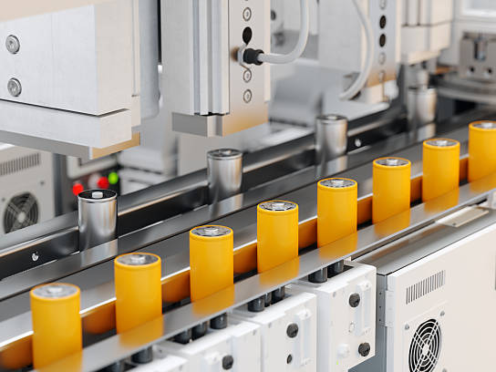
The manufacturing process has three major stages. Electrode manufacturing turns active material powders into precisely coated metal foils the anode and cathode sheets that store and release lithium ions. Cell assembly layers these electrodes with separators inside ultra-dry cleanrooms and injects the electrolyte that enables ion transport. Cell finishing the longest and most expensive stage subjects every cell to its first charge-discharge cycles, forming the critical solid-electrolyte interphase (SEI) layer that determines the cell’s usable life.
The final product takes one of three physical forms. Cylindrical cells the familiar 18650, 21700, and 4680 formats use a wound “jelly-roll” structure inside a rigid metal can. They are favored for mechanical robustness and high-speed manufacturability. Prismatic cells house either wound or stacked electrode assemblies in a rectangular hard case, maximizing packing efficiency in vehicle battery packs. Pouch cells use flexible aluminum-laminate film. They offer the highest gravimetric energy density but demand the most careful handling during assembly.
What makes all of this exceptionally difficult is the precision required. Electrode coatings must stay within ±2 microns of target thickness across kilometer-long foil rolls traveling at 80 meters per minute. Electrode layers must align to within 200 microns during stacking about twice the width of a human hair. The assembly environment demands dew points of -40°C to -60°C, drier than any natural desert on Earth. And every single cell must pass end-of-line electrical testing. One defective cell can take down an entire battery pack.
Underpinning every one of these steps is an extensive fluid control infrastructure pumps, piping, and valves that move, meter, and isolate slurries, solvents, electrolytes, and thermal fluids throughout the factory. Understanding where and why valves matter in battery production is not a footnote. It is essential to designing and operating a reliable manufacturing line.
Key Metrics Overview:
-
Coating Precision: ±2μm
-
Alignment Tolerance: 200μm
-
Assembly Dew Point: −60°C
Electrode Manufacturing The Foundation of Cell Performance
Electrode manufacturing is where battery performance is won or lost. The four sequential steps mixing, coating and drying, calendering, and slitting each carry one non-negotiable quality metric. A defect at any of these steps cannot be corrected downstream. Get the electrode right, and you have a solid foundation. Get it wrong, and even flawless assembly and formation cannot salvage the cell.
Mixing Turning Powders Into Homogeneous Slurry
The entire battery begins as a mixture of powders: active material (lithium metal oxide for the cathode, graphite for the anode), conductive carbon additives, and polymer binders, suspended in a solvent most commonly N-Methyl-2-pyrrolidone (NMP) for cathode processing. The slurry’s quality directly dictates the uniformity of every subsequent manufacturing step.
Two mixing approaches exist. Batch mixing uses planetary mixers large vessels with orbiting blades that shear and disperse the components over 2 to 8 hours per batch. It is well-understood, flexible, and still dominant in pilot lines and smaller-scale production. Continuous mixing via twin-screw extruders feeds raw materials at one end and outputs finished slurry at the other, achieving better homogeneity in minutes rather than hours. The trade-off is higher upfront capital cost and less flexibility for frequent chemistry changes.
The key quality control parameter is viscosity, typically maintained between 3,000 and 10,000 centipoise (cP). Too low, and the slurry settles and stratifies in the coating hopper, causing density gradients across the electrode. Too high, and the coating head cannot deposit a uniform film. Particle size distribution matters equally: active material particles in the 10 20 micron range must be uniformly dispersed, with no agglomerates large enough to tear the coating gap or create localized high-resistance spots.
From a fluid handling perspective, the mixing station demands valves capable of precise ingredient dosing. Ball valves with full-bore, cavity-filled designs prevent slurry accumulation in dead zones where material can dry and contaminate the next batch. Butterfly valves with minimal dead-leg construction handle the abrasive, particulate-laden flows on the discharge side. And because NMP is both a volatile organic compound and a flammable solvent, any valve or actuator in the mixing area must carry ATEX certification for explosion-proof operation.
Coating & Drying Precision Deposition at Speed
Coating is where the slurry meets the foil. A thin layer of electrode slurry is deposited onto metal current collector foil: copper (typically 8 12 μm thick) for the anode, aluminum (12 20 μm) for the cathode. The industry standard is slot-die coating, which forces slurry through a precisely machined gap onto the moving foil web, achieving wet-film thickness uniformity within ±1.5 to 2.0 percent across the full width.
The coated foil then enters a multi-zone drying oven. These ovens can stretch up to 80 meters, with conveyor speeds reaching 80 meters per minute and zone temperatures ranging from 80°C at the entry to avoid skinning over the wet surface to 160°C in later zones where the bulk of solvent removal happens. Convection and infrared heating drive off the NMP. The solvent-laden exhaust air passes through a recovery system typically a condensation or adsorption unit that captures over 90% of the solvent for reuse. This serves both environmental compliance and operating cost: solvent recovery alone can account for approximately 15% of total electrode manufacturing energy consumption.
The fluid control demands at this stage are substantial. The coating head supply pump must deliver pulse-free flow. Any pressure fluctuation translates directly into coating thickness variation. Drying zone air handling requires banks of modulating control dampers to maintain precise temperature profiles across every meter of oven length. In the solvent recovery loop, valves in contact with hot NMP vapor must resist both chemical attack and thermal cycling. Stainless steel 316L is the minimum baseline. PTFE-lined components go where condensed liquid NMP sits in valve bodies between production runs.
Electrode Manufacturing Workflow:
-
Mixing: 3k–10k cP viscosity
-
Coating: ±2μm tolerance
-
Calendering: 10–20 kN/cm
-
Slitting: <10μm burr
Calendering Compressing for Density and Adhesion
After drying, the electrode coating is a porous, loosely adhered layer roughly 40 to 60 percent void space. Calendering passes this coated foil between two heated steel rollers under high pressure, compressing the coating to the target porosity (typically 20 to 40 percent) and bonding it firmly to the current collector.
The calendering parameters are chemistry-specific. A high-energy NMC cathode might be calendered to a density of 3.4 3.7 g/cm³. An LFP cathode, with its inherently lower material density, targets 2.2 2.5 g/cm³. Roll temperatures range from 80°C to 150°C. Linear pressing forces of 10 to 20 kilonewtons per centimeter of roll width are typical. The roller gap is controlled to micron precision. Too loose, and excess porosity limits energy density. Too tight, and the pores collapse so completely that electrolyte cannot wet the electrode during filling crippling rate capability and cycle life. Thickness rebound after calendering, a viscoelastic relaxation effect, must stay below 5 percent. Otherwise the electrode will not fit properly in the cell housing.
The hydraulic or electromechanical systems that position the calender rolls demand stable, responsive pressure control. Pneumatic proportional regulators on the roll-gap actuation system must maintain setpoint within fractions of a millimeter under continuous load. A pressure control valve that sticks or drifts does not stop the line but it produces several hundred meters of out-of-spec electrode before anyone notices.
Slitting & Vacuum Drying Final Electrode Prep
The last two steps prepare the electrode for cell assembly. Slitting cuts the wide “mother roll” into narrower “daughter rolls” matching the final electrode dimensions. The uncoated foil area along one edge becomes the current-collector tab. Traditional mechanical slitting uses rotary knives fast and proven, but blade wear gradually increases burr height. Laser slitting eliminates tool wear entirely and produces cleaner edges with burrs under 10 microns, but requires careful management of the heat-affected zone to avoid degrading the active material near the cut edge. Burr control is not cosmetic: a metal burr tall enough to pierce the separator creates an internal short circuit. In a pack containing thousands of cells, that single defect can trigger thermal runaway.
Vacuum drying is the insurance policy. Coated electrodes absorb trace moisture from ambient air. Even a few hundred parts per million of residual water inside a finished cell will react with the lithium hexafluorophosphate (LiPF₆) electrolyte salt to generate hydrofluoric acid (HF) which etches the cathode, consumes active lithium, and generates gas. Electrodes are baked under vacuum at 80 to 120°C for 6 to 24 hours, bringing residual moisture below 500 ppm or below 200 ppm for moisture-sensitive chemistries like NMC811. The vacuum chamber isolation valves must seal reliably over thousands of cycles. A single leak during the 18-hour bake cycle reintroduces moisture and wastes an entire batch.
Cell Assembly Where Precision Meets Cleanliness
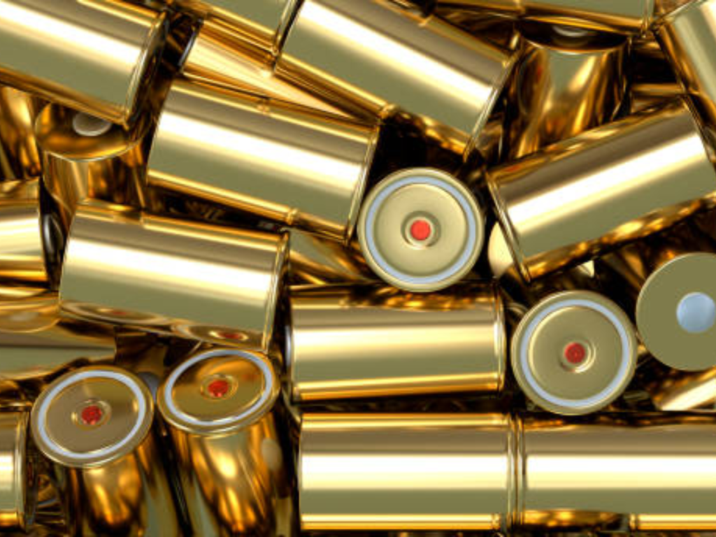
Once the electrodes are ready, the manufacturing environment transforms. Cell assembly takes place inside dry rooms where the dew point is held between -40°C and -60°C equivalent to roughly 0.08 percent relative humidity at room temperature. Workers wear full protective suits not to protect themselves from the product, but to protect the product from themselves. A single fingerprint contains enough moisture and salts to contaminate a cell. The air is filtered to ISO Class 7 or 8 cleanliness. Separate production lines for anodes and cathodes prevent cross-contamination between the two electrode chemistries.
Dry room spec: -40°C to -60°C dew point (~0.08% RH), ISO Class 7 8 cleanroom, separate anode/cathode lines. Workers wear full suits to protect the product from themselves.
Notching & Separation Cutting Electrodes to Shape
Before stacking or winding, the slit electrode rolls must be cut into individual sheets of precise dimensions. The uncoated foil area along one edge becomes the current-collector tab. Mechanical die punching is fast and well-established but suffers from progressive tool wear burr height increases with every thousand strokes, requiring regular maintenance intervals. Laser notching uses a pulsed beam to vaporize the cut path, producing consistent edge quality regardless of cycle count and enabling rapid shape changes through software rather than tooling swaps. The trade-off centers on capital cost and throughput: a mechanical die line runs faster at lower equipment cost, but a laser system eliminates the hidden cost of burr-related defects downstream.
Stacking vs. Winding The Core Assembly Decision
This is the fork in the road where cell format is determined. Winding takes continuous strips of anode, separator, cathode, and a second separator layer, and winds them around a mandrel into a cylindrical or flattened “jelly-roll.” It is the dominant process for cylindrical cells, hitting up to 30 cells per minute from a single winding station. The critical process variable is winding tension. Too loose creates gaps that increase internal resistance. Too tight compresses the separator and reduces its porosity. Uneven tension across the web width causes telescoping defects where layers shift axially. Wound cells naturally have fewer current-collector tabs typically one or two which limits peak power capability but simplifies manufacturing.
Stacking alternately layers individual sheets of anode, separator, and cathode, like building a deck of cards one by one. The Z-folding method uses a single continuous separator strip folded in a zigzag pattern, achieving placement precision within 200 microns. Single-sheet stacking uses robotic vacuum grippers to pick and place individual electrode sheets at rates approaching 0.15 seconds per piece on advanced multi-station equipment. Stacked electrodes produce cells with lower internal resistance and better rate capability because every layer connects directly to a current-collector tab. The trade-off: the equipment is more complex and costs more up front.
Winding vs. Stacking Core Assembly Methods:
| Dimension | Winding (Jelly-Roll) | Stacking (Z-Fold or Single-Sheet) |
| Typical cell format | Cylindrical, some prismatic | Pouch, prismatic |
| Throughput | High (up to 30 ppm) | Moderate (0.15 s/pcs per station) |
| Alignment precision | ±300 500 μm | ±200 μm |
| Internal resistance | Higher (fewer tabs, longer current path) | Lower (every layer has a tab) |
| Equipment complexity | Lower | Higher |
| Capital cost | Lower | Higher |
| Best for | High-volume cylindrical cells | High-power, long-cycle-life cells |
Electrolyte Filling The Precision Dispensing Challenge
Electrolyte filling depends on precision fluid control more than any other assembly step. A typical 5 Ah pouch cell receives 4 to 5 grams of electrolyte LiPF₆ lithium salt dissolved in a blend of organic carbonate solvents with proprietary additive packages. Filling must happen under vacuum to draw electrolyte into every pore of the electrode stack. Fill weight must be accurate to within ±1 to 2 percent. Underfill by even half a gram starves a portion of the electrode of ionic conductivity, creating dead zones that permanently reduce capacity. Overfill wastes expensive electrolyte and risks swelling during formation.
The valve delivering this dose operates under uniquely challenging conditions. LiPF₆ hydrolyzes on contact with moisture to form HF acid. Every wetted surface must be chemically inert stainless steel components need PTFE or PFA lining, and polymer seals must resist both the organic solvents and the trace acid. The dispensing valve must open and close with sub-millisecond repeatability to control shot size. It must seal drip-tight between cycles. Even a single droplet of electrolyte on the cell’s sealing surface prevents a hermetic closure.
Two valve technologies dominate this application. Diaphragm valves use a flexible PTFE or EPDM membrane to isolate the actuator from the fluid path, eliminating dynamic seal leakage. Their wetted surfaces the valve body interior and diaphragm face are easily lined with PTFE or PFA for full chemical compatibility. The trade-off is cycle speed: diaphragm valves run slower than poppet or jet valves, capping throughput on high-speed lines. Piezo-actuated jet valves hit the highest dispensing speeds up to 1,000 Hz on advanced systems by using a piezoelectric stack to rapidly deform a diaphragm, ejecting micro-droplets as small as 0.5 nanoliters. They dominate high-throughput stations but demand meticulous maintenance. Particulate contamination clogs the micro-orifice. Piezo performance degrades above the Curie point.
For both technologies, drip-free shutoff is non-negotiable. A droplet of electrolyte left on the fill nozzle lands on the cell’s heat-seal area, preventing a hermetic seal. The resulting latent failure may not show up until the cell has been in the field for months. The valve’s internal geometry must retract the fluid column slightly at the end of each dispense cycle a feature achieved through careful balancing of supply pressure, orifice diameter, and diaphragm stroke.
Cell Finishing Formation, Aging & Quality Verification
Cell finishing is where the cell becomes electrochemically alive and where manufacturing time and cost concentrate. Formation and aging together occupy one to three weeks of process time and consume roughly one-third of total cell manufacturing cost. The reason is simple: enormous capital tied up in formation cycling equipment, plus the factory floor space needed to hold cells during aging.
Cell Finishing Three Stages at a Glance:
| Stage | Purpose | Key Parameters | Typical Duration | Common Defects Detected |
| Formation | Build the SEI passivation layer on the anode | 0.1C 0.5C charge rate; voltage ceiling 3.0V (LFP) or 4.2V (NMC) | 12 24 hours | Uneven SEI, lithium plating, gas generation |
| Aging | Stabilize electrochemistry; screen for internal micro-shorts | 30 50°C elevated-temperature storage | Days to 3 weeks | Voltage drop >0.05 V/day (self-discharge) |
| End-of-Line Testing | Verify capacity, internal resistance, leakage, and appearance | 100% testing: capacity at 1C, EIS at 1 kHz, leak test | Minutes per cell | Low capacity, high IR, seal failure |
| Internal resistance | Higher (fewer tabs, longer current path) | Lower (every layer has a tab) | ||
| Equipment complexity | Lower | Higher | ||
| Capital cost | Lower | Higher | ||
| Best for | High-volume cylindrical cells | High-power, long-cycle-life cells |
Formation is the cell’s first controlled charge. At low current typically 0.1C to 0.5C lithium ions intercalate into the anode graphite and simultaneously react with electrolyte solvent molecules at the electrode surface. This forms the solid-electrolyte interphase, a nanoscale passivation film. The SEI layer is electrically insulating, which prevents further electrolyte decomposition, but ionically conductive, which lets lithium ions pass through. Its quality determines the cell’s calendar life, cycle life, and safety margin. Formation consumes 5 to 10 percent of the cell’s active lithium inventory lithium permanently bound in the SEI that cannot participate in future charge-discharge cycles.
During formation, gases primarily CO₂ and ethylene evolve from electrolyte decomposition and must be removed. For pouch cells, this means piercing the gas pocket in a vacuum chamber and resealing the final edge. For cylindrical and prismatic cells, formation typically occurs before final sealing, with degassing integrated into the process flow.
Aging follows formation. Its job is quality screening. Cells sit at elevated temperatures (30 50°C) for days to weeks while their open-circuit voltage is monitored. A cell with an internal micro-short caused by a metal particle contaminant or a separator pinhole shows a steadily dropping voltage as the short slowly discharges it. The screening threshold: voltage drop exceeding 0.05 volts per day. Cells that pass aging proceed to end-of-line testing. Cells that fail are scrapped or, for high-value large-format cells, sent for failure analysis.
The thermal management behind this entire stage depends on reliable fluid control. Formation cycling cabinets generate substantial heat. Chilled water loops supplied at 7°C, returning at 12°C must remove it. Aging chambers require precise temperature uniformity across every shelf so every cell ages under identical conditions. Both systems depend on modulating control valves that hold a temperature setpoint within ±1°C. A stuck-open cooling valve can drop chamber temperature by 5°C within an hour, invalidating aging data for thousands of cells.
Precision Fluid Control for Your Production Line: From slurry handling to electrolyte dispensing, every valve decision shapes your yield curve.
The Hidden Backbone Fluid Control Infrastructure in Battery Production
If the electrodes are the muscle and the electrolyte is the blood of a battery factory, the valve network is the circulatory system the arteries and capillaries that move, meter, and isolate every process fluid across every production zone. A wrong valve selection wrong material, dead-leg geometry, or inadequate sealing rarely stops a production line outright. Instead, it erodes yield slowly and silently. The damage shows up months later as a higher warranty-return rate, with a root cause nearly impossible to trace back to a $200 component installed two years earlier. This section maps the four critical fluid control domains in battery cell manufacturing and the valve technologies that serve each.
Slurry & Solvent Handling The Abrasive & Corrosive Frontline
The mixing and coating areas handle the most mechanically and chemically aggressive fluids in the entire factory. Electrode slurry is a dense, abrasive suspension ceramic-adjacent metal oxide particles in a solvent carrier that scores standard stainless steel valve seats within months. NMP, the dominant cathode solvent, aggressively swells common elastomer seals. A Buna-N O-ring can degrade to the point of leakage within weeks of continuous exposure.
Valve Selection: 3 Rules for Slurry & Solvent Lines:
-
Full-bore ball valves with cavity-filled seats no dead zones for slurry accumulation and contamination.
-
Butterfly valves with PTFE/EPDM seats for large-diameter lines where low pressure drop matters more than zero dead volume.
-
ATEX Zone 1/2 certification on every powered valve actuator in mixing and coating areas.
Material compatibility extends to the valve body. Stainless steel 316L is the minimum acceptable grade for wetted components in NMP service. Grade 304, while cheaper, lacks the molybdenum needed to resist chloride traces and acidic byproducts that accumulate in solvent recovery loops. For the most demanding positions concentrated NMP condensate drain valves on the recovery system PTFE- or PFA-lined valve bodies provide near-universal chemical resistance. The higher component cost pays for itself in extended service intervals.
Electrolyte Dispensing Precision Fluid Control at the Microliter Level
Electrolyte filling valves operate at the extreme intersection of precision, speed, and chemical aggression. LiPF₆ in electrolyte reacts with water even atmospheric moisture at ppm levels to produce HF, one of the most corrosive acids in industrial chemistry. A single drop of condensed moisture inside a valve body can generate enough HF to pit a stainless steel seat, creating a leak path that worsens with each cycle.
Two valve technologies occupy different positions on the precision-versus-speed curve. Diaphragm valves use a flexible PTFE or EPDM membrane to isolate the actuator from the fluid path. This eliminates dynamic seal leakage as a failure mode. Wetted surfaces are limited to the valve body interior and the diaphragm face both easily lined with PTFE or PFA for full chemical compatibility. The trade-off: diaphragm valves run at lower frequencies than poppet or jet valves, capping throughput on high-speed lines.
Piezo-actuated jet valves reach the highest dispensing speeds up to 1,000 Hz on advanced systems. A piezoelectric stack rapidly deforms a diaphragm, ejecting micro-droplets as small as 0.5 nanoliters. This technology dominates high-throughput electrolyte filling stations but demands meticulous maintenance. Particulate contamination in the electrolyte clogs the micro-orifice. Piezo actuator performance degrades if exposed to temperatures above its Curie point.
For both technologies, the non-negotiable metric is drip-free shutoff. A droplet of electrolyte left on the fill nozzle after each cycle lands on the cell’s heat-seal area. The seal fails. The latent defect may not appear until months of field service. The valve’s internal geometry must retract the fluid column slightly at the end of each dispense cycle a balance of supply pressure, orifice diameter, and diaphragm stroke.
Cooling & HVAC Utilities The Unsung Thermal Management
Walk into any battery gigafactory and the most visible equipment is the electrode coating line and the cell assembly robots. But the largest continuous energy consumer and the system whose failure halts production fastest is often the HVAC and cooling water infrastructure running quietly above the cleanroom ceiling.
The dry room’s -40°C to -60°C dew point comes from a cascade of air handling units. Each contains cooling coils served by chilled water at 7°C supply temperature, followed by desiccant rotor dehumidifiers that strip residual moisture from the airstream. Modulating control valves on the chilled water coils must respond to dew-point sensor feedback within seconds. If humidity starts rising during a production shift, every cell assembled from that moment forward carries elevated risk of moisture-induced degradation. That damage may not surface until end-of-line testing and by then, thousands of cells may already be affected.
The formation area presents a different thermal challenge. Formation cabinets hold racks of cells undergoing first charge-discharge cycles. Each cell dissipates heat that must be removed to hold the target temperature typically 25°C to 45°C depending on chemistry and formation protocol. Cooling water control valves on each cabinet must keep temperature within ±1°C. Formation temperature directly affects SEI growth kinetics. A 5°C excursion during the first charge cycle produces a measurably different SEI: thicker, more resistive, less stable over calendar life. Across a production run of a million cells, that temperature-induced variance shows up as a wider capacity distribution, more cells falling below the grading threshold, and higher scrap rates.
Automation & Actuation The Shift to Smart Fluid Control
The battery industry’s move from semi-automated pilot lines to lights-out gigafactories is forcing a parallel evolution in how valves are actuated and monitored. Manual valves such as flanged butterfly valves and wafer butterfly valves are stillstill common in older plants and pilot facilities need operators to physically walk the line to open, close, or throttle flow at each process adjustment. This model cannot keep up with the speed and repeatability demands of high-volume cell manufacturing.
Pneumatic vs Electric Actuators:
-
Pneumatic Actuators:
-
Spark-free for ATEX-classified zones.
-
Lowest cost per actuation point.
-
Response times under 100 ms.
-
-
Electric Actuators:
-
Continuous position feedback ±0.5%.
-
DN100+ torque capacity.
-
Closed-loop flow control.
-
-
Note: IO-Link diagnostics enable predictive maintenance flag seal wear before it fails.
Pneumatic actuators dominate battery production for two reasons. They are inherently spark-free, so they are safe for ATEX-classified zones without extra protection circuits. And they cost the least per actuation point. Process lines rely heavily on a wide variety of these automated units, including pneumatic wafer and flanged butterfly valves for large-scale solvent handling, as well as pneumatic 3-piece stainless steel ball valves, pneumatic tri-clamp ball valves, and pneumatic sanitary ball valves for precise slurry and electrolyte isolation. A rack of pneumatic solenoid valves a valve terminal can control dozens of process valves from a single fieldbus node, with response times under 100 milliseconds. The downside: pneumatic actuators consume compressed air continuously. A leaky fitting anywhere in the air distribution network represents a hidden operating cost that compounds 24 hours a day.
Electric actuators are gaining ground in non-classified areas especially on larger valves (DN100 and above) where torque requirements exceed what a compact pneumatic actuator can deliver. Electric actuators provide continuous position feedback, typically ±0.5 percent of span, enabling the closed-loop flow control that pneumatic on-off valves cannot achieve. This matters most on services like cooling water flow to formation cabinets, where precise, modulated flow control directly impacts temperature uniformity and cell quality consistency.
The next step already running in the most advanced gigafactories integrates valve diagnostics into the factory’s SCADA system via IO-Link or fieldbus protocols. An intelligent valve terminal now monitors each connected valve’s cycle count, stroke time, and end-position detection in real time. It flags a valve whose stroke time has increased by 20 percent a sign of seal wear or rising friction before the valve fails in service. This shifts maintenance from reactive (fix it when it breaks) to predictive (replace it during the next scheduled downtime). The result: higher overall equipment effectiveness in an industry where every percentage point of yield improvement means millions of dollars in annual savings.
For engineers specifying the fluid control infrastructure of a new battery production line, the takeaway is straightforward: evaluate the valve and actuator supply chain as rigorously as the coating and stacking equipment. A manufacturer with broad in-house capability across manual valves, electric actuated valves, pneumatic actuated valves, and globe control valves one that delivers material certifications, ATEX documentation, and custom actuation configurations from a single source reduces both procurement workload and the integration risk of juggling multiple component suppliers with incompatible communication protocols and lead times.
Quality at Scale Why Every Component Counts
Battery manufacturing quality follows the 1:10:100 rule familiar to every production engineer. Catch a defect at incoming inspection: $1 to fix. Catch the same defect at end-of-line testing: $10. Let it reach the customer: $100 or far more, if it triggers a field recall involving thousands of battery packs.
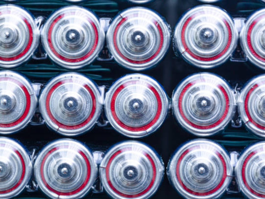
The quality control framework rests on three pillars. Incoming quality control (IQC) verifies raw materials metal foil thickness and surface finish, electrolyte purity and water content, separator porosity and tensile strength before they enter production. In-process quality control (IPQC) monitors critical parameters at every station: slurry viscosity before coating, coating thickness after drying, electrode alignment during stacking, fill weight during electrolyte dispensing. Outgoing quality control (OQC) subjects every finished cell to capacity, internal resistance, and leakage testing.
But a fourth pillar matters just as much and gets far less attention: the reliability of the support systems that make production possible. A diaphragm valve on the electrolyte filling station that drips even intermittently produces cells with insufficient electrolyte. Those cells form an incomplete SEI layer. Six months into field service, capacity fade accelerates. The failure chain is long. The root cause is obscure. The commercial consequence is the same every time: warranty costs, customer dissatisfaction, reputational damage.
At gigawatt-hour scale, the gap between 95 and 98 percent first-pass yield is not three percentage points. It is tens of thousands of additional good cells per day millions of dollars in annual revenue with zero additional capital investment. Closing that gap means treating every component in the production line as a contributor to quality. That includes the valves, actuators, sensors, and controllers too often dismissed as commodity afterthoughts. The factories that internalize this principle will be the ones that win the global race to manufacture better batteries, at higher yield, at lower cost.
Quality Focus: Every component in a battery production line from the slot-die coater to the electrolyte fill valve to the cooling water control valve contributes to final cell quality. In a gigafactory producing millions of cells per year, a 1% yield improvement from better fluid control reliability can translate to millions of dollars in additional revenue.Engineer Your Fluid Control Infrastructure: From slurry mixing to electrolyte filling, every valve in your production line is a quality decision. Let’s build a fluid control specification that matches your manufacturing ambition.
References
-
PEM RWTH Aachen / VDMA. “Battery Cell Production Guide” (5th Edition). Available at: https://www.pem.rwth-aachen.de/
-
Attia, P.M. et al. “Challenges and opportunities for high-quality battery production at scale.” Nature Communications, 2025. Available at: https://www.nature.com/articles/s41467-025-55861-7
-
Kampker, A., Heimes, H. et al. “Approach for Data-Based Optimization in Cell Finishing of Battery Production.” CPSL Conference, 2023. Available at: https://www.repo.uni-hannover.de/handle/123456789/13600
-
BatteryDesign.net. “Formation & Aging.” Available at: https://www.batterydesign.net/manufacture/cell-manufacturing/battery-cell-manufacturing-process/formation-aging/
-
Festo AG. “Automation for Battery Manufacturing.” Available at: https://www.festo.com/cn/en/e/solutions/industry-segments/electronics-industry/battery-manufacturing-id_6949/
-
Emerson Electric. “Lithium-Ion Battery Manufacturing Solutions.” Available at: https://www.emerson.com/en/corporate/industries/chemical/specialty-chemical/lithium-ion-battery-manufacturing
-
GEMÜ Group. “Valve Solutions for Mixing Electrode Slurries in Li-ion Cell Manufacturing.” ValveUser, 2022. Available at: https://www.valveuser.com/show-article.asp?id=3773
-
Meech International. “Industry specialist warns of the common threat of contamination in EV battery production.” Renewable Energy Magazine, 2025. Available at: https://www.renewableenergymagazine.com/storage/industry-specialist-meech-warns-of-the-common-20250411
-
Coesia Group. “Integrated Solutions for Battery Cell Manufacturing Lines.” 2026. Available at: https://www.coesia.com/en/news/integrated-solutions-for-battery-cell-manufacturing-lines
-
E-Mobility Engineering. “Battery Cell Manufacturing: From Coin Cells to Large-Scale Production.” Available at: https://www.emobility-engineering.com/battery-cell-manufacturing/
-
VINCER Valve. Electric Actuated Valves. Available at: https://www.vincervalve.com/electric-actuated-valve/
-
VINCER Valve. Globe Control Valves. Available at: https://www.vincervalve.com/vincer-globe-control-valves/
-
VINCER Valve. Homepage. Available at: https://www.vincervalve.com/
 English
  French
  Spanish
  Italian
  German
  Dutch
Dutch  Portuguese
  Korean
  Russian
  Chinese
  Finnish