Introduction
In the high-stakes realm of industrial automation, whether you are managing a massive multi-stage desalination plant, a stringent hygienic food processing facility, or an intricate high-pressure petrochemical pipeline, the margin for operational error is effectively zero. Every fluid, volatile gas, or abrasive slurry traversing through your system architecture must be controlled with absolute, unwavering precision. At the beating heart of this automated control system lies a mechanism that translates raw, unrefined energy into exact, repeatable mechanical movement. Among the vast myriad of technologies available to modern engineers, the rack and pinion valve actuator stands out as an unparalleled engineering marvel of reliability, speed, and volumetric efficiency.
However, selecting the correct actuator for a highly specialized pipeline is not merely a rudimentary matter of matching pipe diameters. Senior project engineers and plant procurement managers frequently encounter catastrophic system failures, premature seal wear, and exponentially ballooning maintenance costs simply due to inadequate initial sizing, ignorance of pressure derating, or an incomplete understanding of the actuator’s internal mechanics and material compatibility. This ultimate guide is designed to deconstruct the technical DNA of these devices, moving beyond surface-level definitions to explore the critical variables—such as torque curve profiling, dynamic friction safety factors, network pressure drops, and ROI-driven selection criteria—that dictate the long-term operational success of your plant.
What is a Rack and Pinion Actuator?
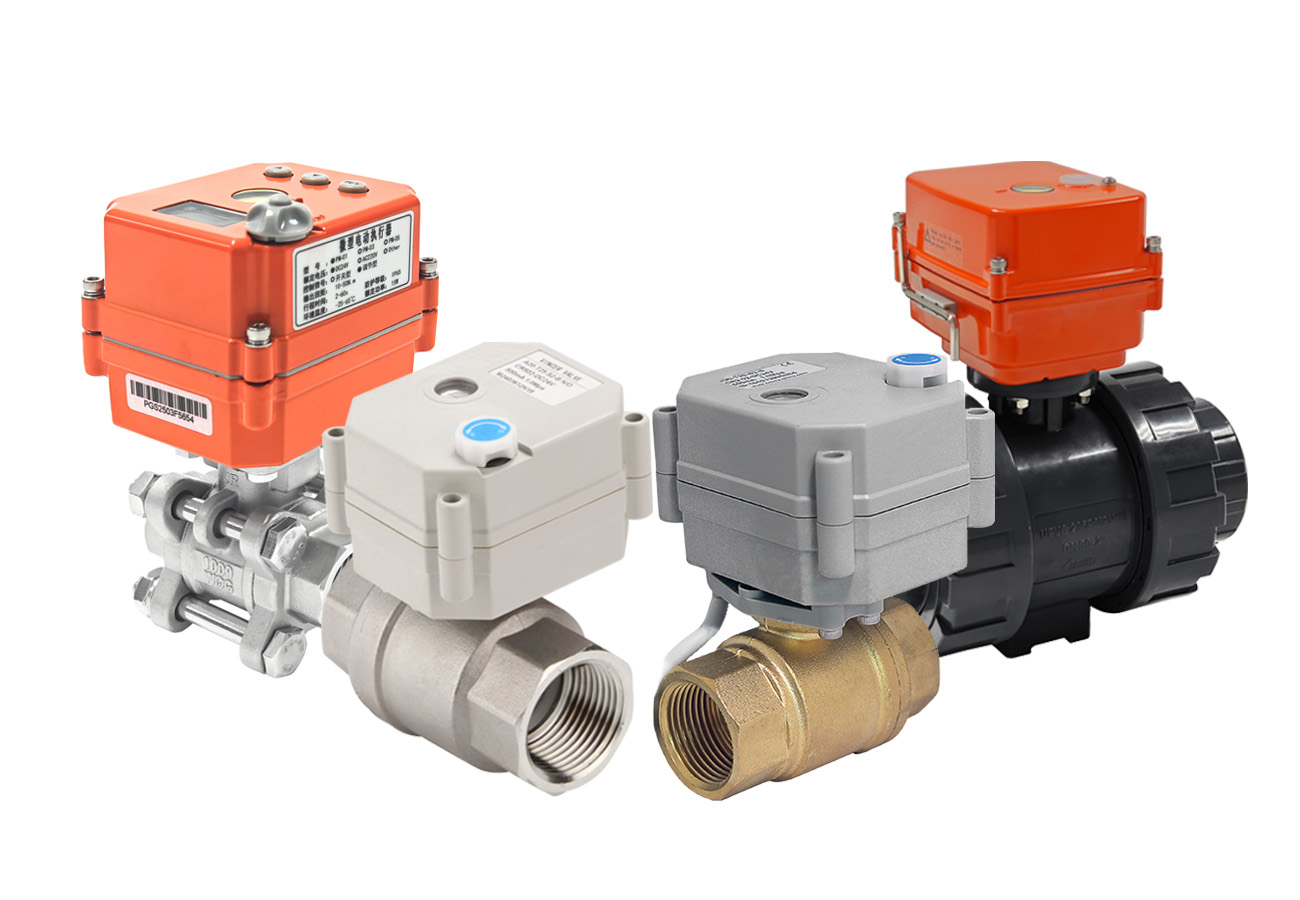
To fully demystify this critical component, we must break it down to its most fundamental physical purpose. In the strictest mechanical terms, a rack and pinion actuator is a robust device engineered to seamlessly and highly efficiently convert linear motion (movement in a straight line generated by pneumatic pressure or electrical force) into rotary motion (turning movement on a fixed axis), or vice versa depending on the specific industrial application.
In the specialized sector of process automation and fluid control, it is specifically designed to service and control “Quarter-turn” (0° to 90°) valves. The most common examples of these are industrial ball valves, high-performance butterfly valves, and plug valves. These types of quarter-turn valves only require exactly a 90-degree rotation to completely transition from a fully open, maximum-flow state to a fully closed, bubble-tight shutoff state. When a Programmable Logic Controller (PLC) or Distributed Control System (DCS) sends an electronic command, the actuator executes the heavy physical labor of turning the valve stem against the tremendous friction of the pipeline media.
The Kinematic Steering Wheel Analogy
To visualize the internal forces, imagine the steering system in a traditional automobile. When you turn the steering wheel (the rotary input), a pinion gear connected to the steering column turns against a linear track outfitted with precision teeth (the rack). This action pushes the rack left or right, turning the wheels. An industrial actuator rack and pinion system operates on the exact same fundamental mechanical principle, but the flow of energy is reversed: the immense linear force (provided by compressed air) pushes the rack, which forces the central pinion gear to rotate, thereby turning the valve stem with massive torque.
The Core Mechanism: How Rack and Pinion Actuators Convert Motion
Understanding the exact thermodynamic mechanics and gear kinematics inside the aluminum housing is absolutely crucial for diagnosing potential field failures and ensuring correct initial specification. While the overarching mechanical concept remains constant, the sequence of operation depends entirely on the driven power source. We must analyze how the involute gear profile maintains zero backlash under high-frequency operation, and how pressure differentials perform precise mechanical work within the cylinder.
Linear to Rotary Conversion (Pneumatic Driven)
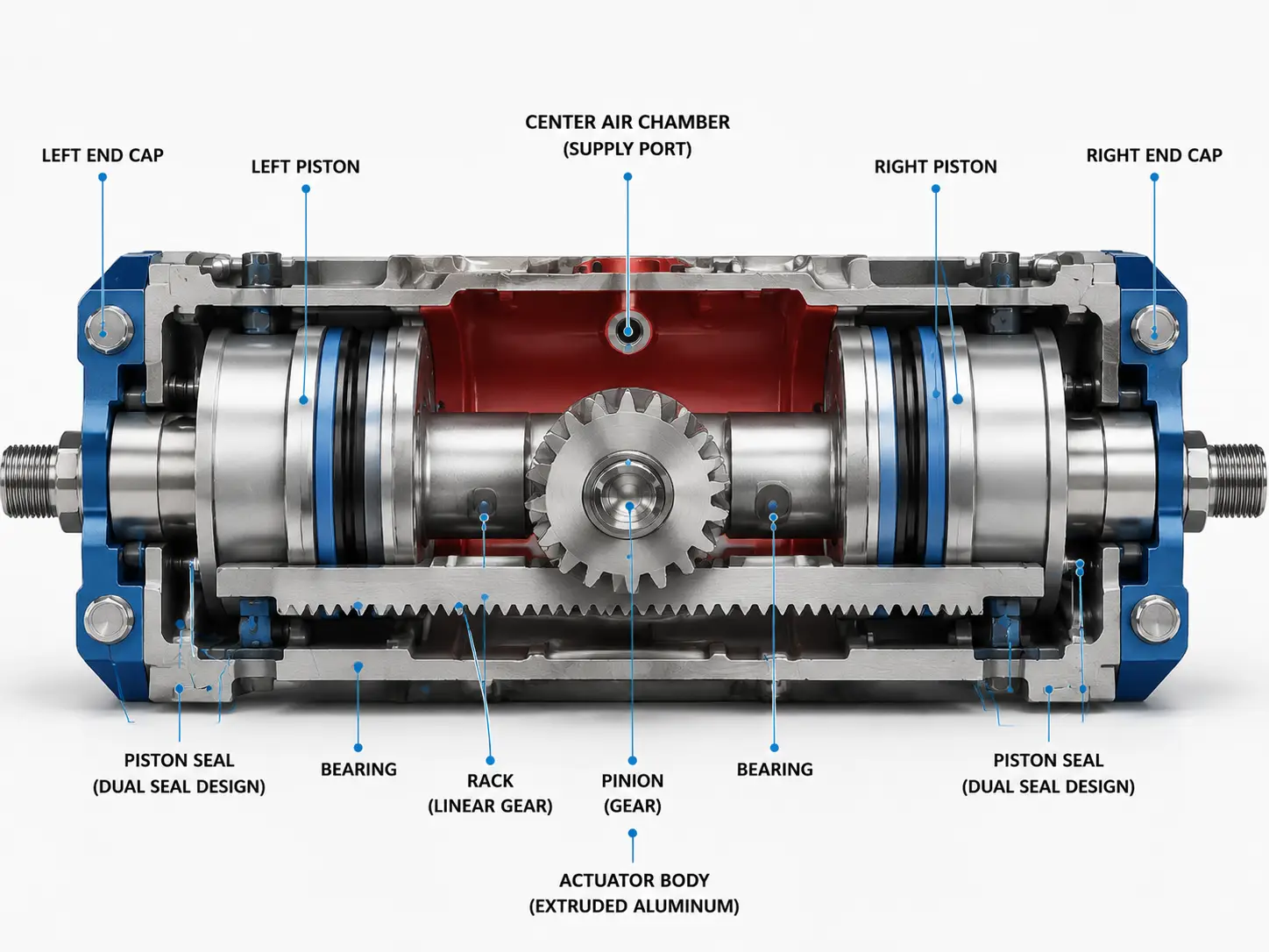
The vast majority of applications in process automation rely exclusively on the pneumatic rack and pinion actuator. These specific devices utilize the potential energy of compressed instrument air to generate massive amounts of linear pushing force. The true genius of the modern industrial design lies in a balanced mechanical configuration known among engineers as the “Opposed Piston Design”.
To understand why these devices are so reliable, we must analyze the step-by-step physical breakdown of the actuation cycle, tracing the air from the compressor to the final mechanical output:
- Pressurization & Mass Injection: Clean, dry, compressed air is directed through a standard threaded port (usually conforming to NAMUR standards) directly into the central chamber of the actuator housing. This highly dynamic process relies on continuous mass injection and pressure differential balancing. As the compressor forces air mass into the confined chamber, it creates a high-pressure zone that vigorously seeks equilibrium against the ambient pressure and the static mechanical friction of the pistons.
- Linear Displacement: This severe pressure differential acts uniformly upon the surface area of two opposed pistons. Following the foundational physics principle of Force = Pressure × Area, the compressed air mass forces the two pistons outward, away from each other in a perfectly straight, linear line towards the end caps.
- Rotary Engagement (Involute Tooth Profile): The inner face of each piston is equipped with an integrated, precision-machined linear gear, known as the “rack”. These racks utilize a precise involute tooth profile to ensure perfect meshing and extremely low backlash. As the pistons move linearly in opposite directions, the racks simultaneously turn the pinion gear counter-clockwise, thereby opening the valve.
The opposed piston design is an absolute engineering necessity for balancing kinetic loads. By having two pistons pushing on strictly opposite sides of the pinion simultaneously, the side-load forces are perfectly mathematically canceled out. This creates a beautifully symmetric, highly stable, and constant torque output, ensuring the valve stem is not subjected to destructive lateral bending forces. Think of two Sumo wrestlers of identical weight standing back-to-back, pushing in opposite directions to rotate a massive turnstile—the structure remains perfectly balanced on its axis.
Rotary to Linear Conversion (Motor Driven)
While the industrial fluid control sector relies almost exclusively on the linear-to-rotary sequence to operate quarter-turn valves, the geometric principle of the mechanism is fully mechanically reversible. To acknowledge its broader application in factory automation, it is important to briefly observe its reversed function. In this configuration, which you will not find turning a butterfly valve, the energy flow is inverted.
A rotary power source—typically an electric servo motor—is attached directly to the central pinion gear. As the motor turns the pinion, the gear physically travels along a stationary linear rack, translating the rotational energy into precise linear positioning. While you will not find this reversed configuration turning a pipeline butterfly valve, this principle is the mechanical backbone of automated linear guide rails, robotic transfer arms, and gantry positioning systems throughout modern manufacturing floors, highlighting the incredible versatility of the rack and pinion mechanical concept.
Double Acting vs. Spring Return Actuators
Once the foundational power mechanics are established, the next critical fork in the fluid control engineer’s journey involves pipeline safety and catastrophic failure mode planning. Should the industrial system suddenly lose compressed air pressure or electrical power during a severe weather event, a grid blackout, or a localized compressor failure, what exactly happens to the valve position? This fundamental safety question dictates the choice between double acting and spring return (single acting) configurations in an actuator rack and pinion assembly.
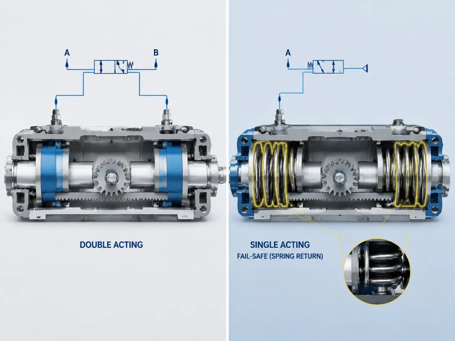
Double Acting: Maximizing Symmetrical Torque
A double acting pneumatic actuator relies entirely on the continuous presence of compressed air to execute both the opening and the closing cycles of the valve stroke. To open the valve, an external solenoid valve directs air into the central chamber to forcefully push the opposed pistons outward. To close the valve, the solenoid exhausts the central chamber and simultaneously redirects the high-pressure air to the two outer end-caps, pushing the pistons inward back to their starting position.
Because there are no heavy mechanical springs fighting against the expanding air pressure at any point in the cycle, a double acting rack and pinion valve actuator utilizes 100% of the aerodynamic force for rotational work. This allows the device to deliver a completely constant, symmetrical, and predictable torque output across the entire 0° to 90° rotational stroke. Furthermore, without the necessity of housing large spring packs, double acting units are significantly more compact and carry a lower initial capital cost.
Ideal Engineering Scenario: This double-acting configuration is highly cost-effective and perfectly suited for non-critical flow systems, such as standard cooling water loops, low-risk mixing tanks, or non-hazardous utility lines. In these specific applications, a sudden loss of plant air pressure that leaves the valve stalled and immobilized in its “last position” (Fail-in-Place) will not trigger a catastrophic environmental spill or compromise plant safety.
Critical Engineering Note: Please note that to successfully maintain this Fail-in-Place state against the immense dynamic Hydrodynamic Torque of high-velocity fluids rushing past the valve disc, a true air-fail system must be explicitly equipped with an Air Lock Valve. This critical accessory hermetically seals the pneumatic circuit, physically locking the remaining pressure inside the cylinder to prevent the hydrodynamic forces from forcing the valve open.
Spring Return: Fail-Safe Mechanisms for Critical Systems
Conversely, for hazardous environments, high-pressure steam lines, or toxic chemical pipelines, a spring return actuator is absolutely mandatory according to international safety codes and SIL (Safety Integrity Level) directives. In this highly complex mechanical design, air pressure is only used to push the pistons in one direction (usually to open the valve). As the pistons move outward, they simultaneously compress a set of heavy-duty, high-tensile mechanical springs housed inside the extended end-caps.
If the air supply unexpectedly fails, the stored potential mechanical energy within these compressed springs immediately takes over, automatically forcing the pistons back to their original resting position without requiring any external power. In the petrochemical and oil & gas sectors, this is formally defined as a Fail-Safe mechanism. Depending on how the actuator is physically mounted to the valve stem, it can be configured as either “Fail-Close” (instantly shutting off the flow of a highly flammable gas to isolate a leak) or “Fail-Open” (instantly opening a pressure relief valve to vent an overheating reactor vessel safely).
The Water Hammer Hazard & Hydraulic Dampening
A highly common and incredibly dangerous engineering misconception is that a spring return fail-safe mechanism should be allowed to instantly “snap” or “slam” the valve shut during a power failure to stop the flow as fast as possible. In high-pressure liquid pipelines, an instantaneous valve closure creates a massive, supersonic kinetic shockwave within the fluid column known as the ‘water hammer’ effect (or fluid transient). This immense pressure spike can literally tear welded pipe flanges apart, severely rupture gaskets, and permanently destroy expensive upstream centrifugal pumps.
To prevent this catastrophic kinetic energy transfer, premium pneumatic actuator setups must be explicitly engineered to decelerate the spring force. This is achieved by installing calibrated exhaust restrictors (which bottleneck the escaping air to create a pneumatic cushion) or external Hydraulic Dampers. These critical accessories actively counteract the spring’s violent expansion, slowing down the final degrees of the stroke speed. This ensures a safe, mathematically controlled deceleration of the fluid column rather than a violent, destructive mechanical slam.
Pneumatic vs. Electric Configurations and ROI Optimization
While the mechanical internal workings dictate safety, the choice of the primary power source dictates the long-term financial viability of the plant. Project engineers are frequently caught in the debate between pneumatic and electric power configurations. Making the correct choice requires looking far beyond the initial purchase order and conducting a rigorous Total Cost of Ownership (TCO) analysis over a multi-year timeline.
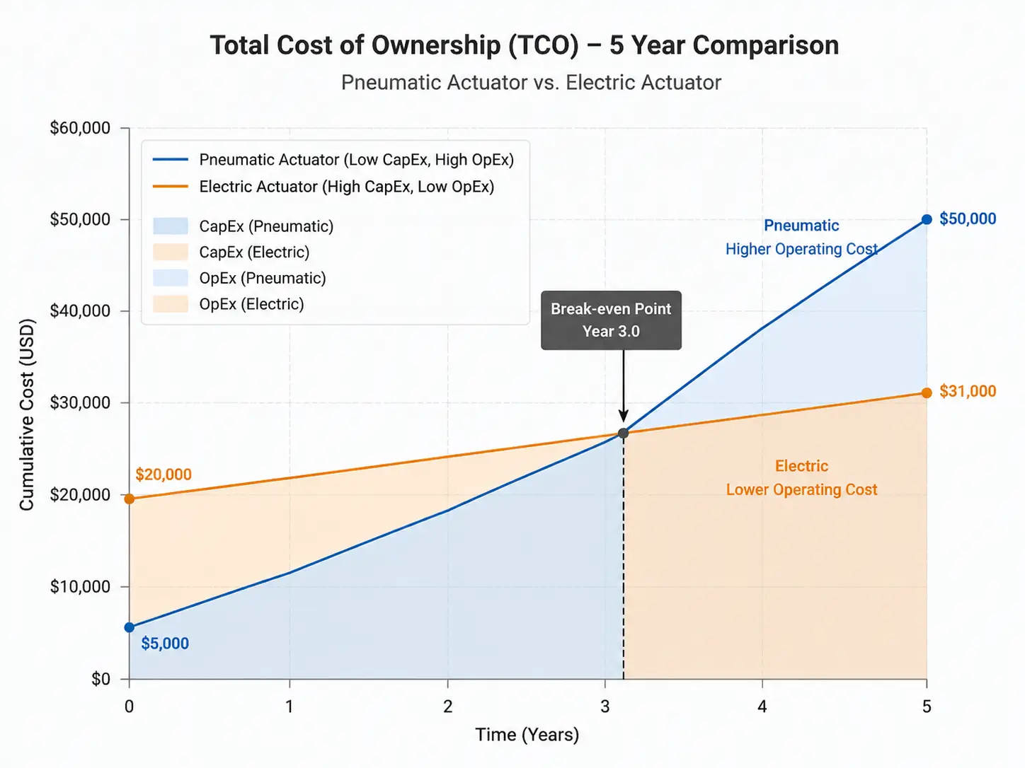
When evaluating automation solutions for a new facility, procurement teams often balk at the extremely high initial capital expenditure (CapEx) of electric actuators, which can easily be 3 to 5 times more expensive than their pneumatic rack and pinion actuator counterparts. Consequently, pneumatic systems dominate the market. However, pneumatic systems are absolutely not “free” to operate. They require industrial air compressors, which are inherently inefficient thermodynamic machines. In a typical manufacturing plant, up to 30% of the electrical energy consumed by the compressor is instantly lost to heat generation, and another 10% to 20% is routinely lost through microscopic leaks in an aging pipe grid.
If a facility does not already possess a robust, high-capacity compressed air infrastructure, or if the control valve is located kilometers away from the main compressor room, the continuous electricity costs required just to maintain pipeline air pressure will soar exponentially. Industry energy audits consistently demonstrate a distinct financial crossover:
• A standard pneumatic actuator might cost only $300 upfront but consume $500/year in continuous compressed air electricity (due to 20% grid leakage and inherent compressor inefficiency), totaling $2,800 over 5 years.
• An equivalent electric actuator might cost $1,500 upfront but consume only $50/year in highly intermittent, on-demand electricity, totaling $1,750 over 5 years.
Financial Result: A clear CapEx vs. OpEx break-even intersection typically occurs around month 36, after which the electric configuration yields pure savings.
Conversely, if the plant already operates a massive, highly efficient, and perfectly maintained compressed air network (such as in a large-scale centralized chemical refinery), the pneumatic rack and pinion actuator remains the undisputed champion of ROI due to its incredibly low maintenance requirements, extremely fast actuation speeds, and cheap component replacement costs.
Decoding the Torque Curve and Sizing
The most common and financially devastating mistake made by inexperienced procurement teams is selecting rack and pinion actuators based solely on a catalog’s “maximum output torque” matching the valve’s nominal requirement. Professional fluid control engineering, guided by rigorous institutions like the ISA (International Society of Automation), dictates a much more profound mathematical analysis of the dynamic torque curve and real-world operational variables.
Understanding Breakaway, Running, and Ending Torque
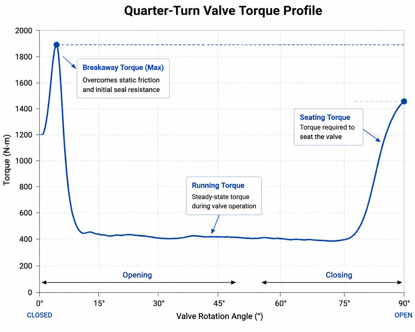
When you actuate an industrial valve under live pipeline pressure, the physical force required is never a flat, constant line. Consider the kinetic physics of pushing open a heavy, slightly rusted iron vault door. The initial, massive kinetic push required to break the static friction of the seals and unseat the ball or disc is immense—this is universally known as the Breakaway Torque. Once the valve is in motion, the hydrodynamic forces of the flowing fluid often help it along, requiring significantly less mechanical force (Running Torque). Finally, to firmly snap the valve shut, compress the elastomer seats against the pipeline pressure, and achieve a bubble-tight seal, an extra terminal surge of force is needed (Ending/Seating Torque).
For a spring return pneumatic actuator, we must also factor in Hooke’s Law of elasticity. As the heavy-duty springs physically extend to close the valve, their mechanical pushing force linearly decreases. Therefore, the absolute weakest point of the actuator’s entire mechanical cycle is the “Spring End Torque” (the final pushing force the springs can generate at the exact moment the valve reaches 0°). If this specific mechanical value drops below the valve’s required Seating Torque, the valve will simply not close tightly, leading to highly dangerous internal media leakage across the closed pipeline.
Calculating the Crucial Safety Factor
The baseline torque values published by valve manufacturers are tested in sterile laboratory conditions using clean water at ambient temperatures. The real industrial world is entirely unforgiving. Therefore, applying a calculated Safety Factor is a non-negotiable engineering requirement to prevent actuator stalling during critical operations.
Advanced Sizing Guidelines & Network Pressure Derating:
- Media-Specific Safety Factors: For clean, naturally lubricating fluids (e.g., filtered water, light hydraulic oils), engineers must add a minimum 20% to 30% safety factor to the baseline torque. For dry, non-lubricating gases or high-temperature steam, add 30% to 40%. For highly abrasive slurries or dry powders, a safety factor of 50% or higher is mandatory, as particulate buildup will severely increase the friction on the valve trim over its lifecycle.
- The Pressure Drop Derating Trap: Never size an actuator based on the optimal air pressure generated inside the main compressor room. If a factory specifies a nominal 5 bar (72 psi) air supply, the actual aerodynamic pressure at the very end of a long, complex pipe network during peak facility usage might severely drop to 4 bar (58 psi). Because a pneumatic actuator’s torque output is directly and linearly proportional to the supplied air pressure, a pressure drop from 5 bar to 4 bar results in an instant 20% loss of output torque. Professional rule of thumb: Always calculate your actuator size based on the minimum guaranteed worst-case pressure at the valve’s specific pipeline location, never the theoretical maximum.
Failure Modes, Seal Degradation, and Maintenance
Even the most robustly constructed mechanical devices will eventually face the harsh realities of industrial wear and tear. To achieve a MECE (Mutually Exclusive, Collectively Exhaustive) understanding of actuator failure modes, engineers must strictly separate the internal mechanisms from the external atmosphere. The internal mechanism of an actuator only ever processes compressed air, while the attached valve handles the actual pipeline fluid. Therefore, actuator failures are dictated by three distinct physical modes.
First, internally, the most prevalent “silent killer” in pneumatic automation is dynamic seal degradation. If the facility’s compressed air is unlubricated, excessively hot, or contaminated, standard NBR (Nitrile) piston O-rings will rapidly harden, crack, and cause “blow-by” (air leaking past the piston, resulting in severe torque loss). Second, externally, harsh atmospheric conditions—such as heavy salt spray on offshore oil rigs or caustic washdowns in food plants—will chemically attack the aluminum housing, causing severe pitting and structural decay. Finally, from a pure kinematic perspective, high-frequency actuation (millions of open/close cycles) will eventually lead to microscopic fatigue wear on the gear tooth meshing surface between the rack and the pinion, increasing backlash and severely reducing positioning accuracy.
Mitigating Risk Through Comprehensive 8-Dimension Engineering
To eliminate these multi-faceted failure modes at the source, professional industrial automation providers abandon the basic “one-size-fits-all” catalog approach. For instance, Vincer Valve, a recognized high-tech enterprise with over a decade of dedicated fluid control expertise, employs an industry-leading 8-Dimension Analysis Methodology for every single project requirement. Before any manufacturing begins, their dedicated engineering team rigorously evaluates the Medium, Temperature, Pressure, Connection Standard, Control Method, Material Requirements, Industry Characteristics, and precise Installation Space.
Drawing from an extensive, highly customizable inventory of over 50 specific material combinations, the actuator is matched perfectly to both its internal duty cycle and its external environment. For example:
- Internal Dynamic Resilience: To combat high-frequency friction heat and ensure long-term reciprocating performance without blow-by, Vincer upgrades the internal piston seals to premium imported FKM, drastically outlasting standard seals in demanding, high-temperature pneumatic environments.
- External Environmental Armor: For highly corrosive external atmospheres, such as offshore marine platforms exposed to constant salt spray, standard extruded aluminum is insufficient. Vincer mitigates this by offering specialized anti-corrosion epoxy coatings, or entirely upgrading the housing to SS316L stainless steel. This ensures the actuator’s structural integrity remains uncompromised even in the most brutal ambient atmospheres.
Industry Standards and Interface Configurations
Finally, a perfectly sized and brilliantly engineered actuator is completely useless if it cannot physically connect to your valve or communicate with your digital control network. The industrial automation sector has strictly standardized these mechanical and pneumatic connections to ensure modular compatibility across global equipment brands. When specifying your actuator rack and pinion, ensure absolute conformance to these primary interfaces:
- ISO 5211 (The Mechanical Foundation): This is the universal global standard specifying the exact bolt circle dimensions of the bottom mounting flange and the geometric shape of the drive shaft (usually a star or square drive). This guarantees the actuator will mate flawlessly to the top of the valve stem without wobbling or introducing mechanical hysteresis.
- NPT or BSP (The Air Supply): Depending on your geographical region (North America heavily utilizes NPT threads, while Europe and Asia default to BSP), ensuring the correct thread standard on the pneumatic ports prevents frustrating air leaks and cross-threading during site commissioning.
- NAMUR (The Automation Ecosystem): NAMUR standardizes the mounting patterns for all external automation accessories, essentially transforming a “dumb” mechanical cylinder into a “smart”, fully integrated automated node.
To create a complete closed-loop control system, an actuator relies on two critical NAMUR accessories:
- The Solenoid Valve (The Brain): Bolted directly to the standardized side NAMUR interface, the solenoid valve receives the low-voltage electrical command (e.g., 24VDC) from the PLC and physically redirects the high-pressure compressed air into the correct actuator chamber to open or close the valve.
- The Limit Switch Box (The Eyes): Mounted securely to the top NAMUR pinion shaft, this electromechanical device physically tracks the actual rotation of the actuator. It sends a continuous electronic signal back to the DCS/control room, providing absolute, real-world confirmation that the valve has successfully reached its intended fully open or fully closed position.
Secure Your Pipeline’s Future with Uncompromising Precision
Ensure the long-term reliability of your fluid control systems by partnering with a manufacturer that prioritizes extreme engineering precision and intelligent solution design.
Operating under strict ISO9001, CE, RoHS, SIL, and FDA certifications, Vincer Valve guarantees that every component meets rigorous international standards. With an agile supply chain capable of delivering standard configurations in just 7 to 10 working days—and providing comprehensive technical proposals within 24 to 48 hours—Vincer is uniquely positioned to accelerate your project deployment without sacrificing engineering quality.