Core Components and Cell Formats — What Goes Into a Lithium-Ion Battery
Every manufacturing step that follows exists to assemble four components into one of three form factors with perfect precision. Before diving into the production line, it helps to know what we are building.
A lithium-ion cell has four essential layers. The cathode (positive electrode) is typically a lithium metal oxide — either NMC (LiNiₓMnₓCo₁₋₂ₓO₂) delivering higher energy density, or LFP (LiFePO₄) offering better thermal stability at roughly 30–40% lower energy density. The anode (negative electrode) is almost always graphite coated onto copper foil. Between them sits a microporous separator — a polypropylene or polyethylene film just 9–25 μm thick with 40–50% porosity — that prevents physical contact while allowing lithium ions to pass. The electrolyte fills every pore: a 1.0–1.2 M solution of LiPF₆ salt dissolved in a mixture of organic carbonates (EC, DMC, EMC).
These four layers are packaged into one of three cell formats:
| Form Factor | Structure & Assembly Method | Typical Applications |
|---|---|---|
| Cylindrical | Electrodes wound into a “jelly roll,” housed in a steel or aluminum can | Power tools, laptops, Tesla EVs (18650, 21700, 4680) |
| Prismatic | Stacked or wound electrode sheets inside a rigid rectangular metal case | EVs, energy storage systems, industrial equipment |
| Pouch | Stacked or Z-folded layers sealed inside an aluminum-laminated polymer film | Consumer electronics, slim devices, some EV modules |
The format choice shapes every downstream manufacturing decision — winding versus stacking, housing material, electrolyte fill volume, and even the formation protocol. But regardless of the final shape, the production journey follows the same three-stage sequence: electrode manufacturing, cell assembly, and cell finishing.
Electrode Manufacturing — From Raw Powder to Precision-Coated Foil
The electrode is the battery’s performance foundation. Coating uniformity, density, and thickness tolerance directly determine the cell’s final capacity, internal resistance, and cycle life. The core tension running through all five electrode steps is this: how do you achieve micron-level precision at production speeds of 60–100 meters per minute?
Mixing and Slurry Preparation — The Formula That Defines Performance
The cathode slurry is the battery factory’s equivalent of a closely guarded recipe. A typical formulation weighs in at roughly 94% active material (NMC or LFP powder), 3% conductive carbon black, and 3% PVDF binder by weight — all dispersed in NMP (N-methyl-2-pyrrolidone) solvent to achieve a target viscosity of 3,000–8,000 centipoise. The anode slurry follows a similar logic but uses graphite active material, a different binder system (usually CMC/SBR in water), and targets a lower viscosity range of 2,000–4,000 cP.
Mixing happens inside planetary mixers or high-speed dispersers under vacuum (≤ -0.09 MPa) to pull out entrapped air bubbles. Water content in the NMP must stay below 300 ppm — any excess moisture attacks the PVDF binder and degrades slurry stability. The finished slurry is checked for particle fineness (≤ 25 μm) and solid content (50–70%), then transferred to the coating line through sealed piping.
Coating — Laying Down the Electrode with Micron-Level Precision
Coating is where precision engineering meets high-speed manufacturing. The cathode slurry is applied to 12–20 μm aluminum foil; the anode slurry goes onto 8–12 μm copper foil. The dominant technology is slot-die coating — a precision extrusion head with a lip gap of 100–300 μm that lays down a continuous wet film at speeds of 60–100 m/min on a roll-to-roll line.
The target dry-film thickness ranges from 50–150 μm for the cathode and 50–100 μm for the anode, with an areal-density tolerance of ±1.5%. Any deviation shows up later as capacity variation between cells. Common coating defects — pinholes, orange-peel texture, longitudinal striping, and edge thickening — each carry a distinct failure signature: pinholes create local hot spots, edge beads cause stacking misalignment downstream, and striping produces uneven current distribution during cycling.
Drying — Removing Solvent Without Cracking the Electrode
As the coated foil exits the slot-die head, it enters a multi-zone drying oven. Temperature ramps through three zones — roughly 50–80°C, then 100–120°C, then 130–150°C — to drive off the NMP solvent without triggering binder migration. Dry it too fast, and the surface skins over, trapping solvent inside and forming cracks when it eventually escapes. Dry it too slow, and the line speed drops below profitability.
Residual moisture after drying must fall below 500 ppm. Meanwhile, the evaporated NMP — 200–500 kg per hour from a single coating line — is captured and routed to a solvent recovery system. At an industrial NMP price of $2–3/kg, a line that vents solvent to atmosphere is burning over a thousand dollars per hour.
Calendering — Compressing the Electrode to the Perfect Density
The dried electrode passes through a pair of heavy rollers applying 50–100 N/mm of linear pressure. This calendering step crushes the porous coating to its target density: 3.4–3.8 g/cm³ for NMC cathodes and 1.4–1.7 g/cm³ for graphite anodes, leaving a porosity of 25–35% (cathode) and 30–40% (anode).
This is the direct trade-off between energy density and power capability. Higher compaction packs more active material into the same volume — boosting energy density — but closes the pore channels that lithium ions need to travel through, reducing rate capability. A thickness rebound of less than 5% after calendering confirms the electrode has been compressed to a stable state.
Slitting and Cutting — Shaping Electrodes for the Final Cell
The calendered “mother roll” is slit lengthwise into narrower daughter coils, then die-cut or laser-cut into individual electrode sheets sized for the target cell format. Dimensional tolerance is ±0.1 mm. The hidden danger here is burrs — metal slivers at the cut edge. If a burr exceeds 15 μm (roughly one-fifth the diameter of a human hair), it can pierce the separator during assembly and create an internal short circuit. This is the first physical safety gate in the production line.
The cut electrodes then enter a vacuum oven at 80–110°C for 6–24 hours, driving residual moisture below 100 ppm before moving into the dry room for assembly.
3,000–8,000 cP
50–150 μm dry film
Residual H₂O <500 ppm
3.4–3.8 g/cm³ (NMC)
Burr control <15 μm
Cell Assembly — Building the Electrochemical Heart
Lithium-ion cell assembly takes place in dry rooms with dew points as low as -60°C — drier than the Sahara Desert by orders of magnitude. The reason is unforgiving chemistry: any moisture that enters the cell during assembly reacts with LiPF₆ electrolyte to form hydrofluoric acid (HF), which attacks the cathode and releases oxygen, setting the stage for thermal runaway.
Winding vs. Stacking — Two Philosophies of Electrode Assembly
The prepared anode, separator, and cathode sheets must now be combined into a cell. Two competing philosophies govern this step.
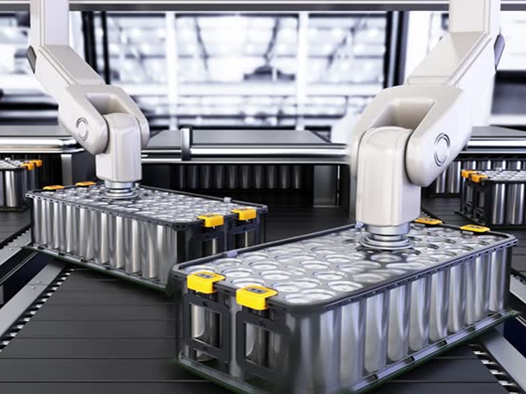
Winding rolls the three layers into a cylindrical or flattened “jelly roll” at speeds of 2–4 seconds per 18650-sized cell. Tension control is the critical variable — ±0.1 N precision keeps the layers aligned within 0.3 mm. Winding is fast, mature, and well-suited to cylindrical formats.
Stacking lays individual electrode sheets and separator layers in alternating sequence — either Z-folded from a continuous separator roll or assembled as discrete sheets. Alignment tolerance tightens to ±0.2 mm, and the process is inherently slower than winding. But stacking achieves 3–5% higher space utilization inside prismatic and pouch cells, and the uniform layer pressure produces lower internal resistance.
The trade-off table looks like this:
| Dimension | Winding | Stacking |
|---|---|---|
| Best format | Cylindrical, some prismatic | Prismatic, pouch |
| Production speed | 2–4 sec/cell (18650) | Slower (discrete steps) |
| Space utilization | Baseline | +3–5% |
| Internal resistance | Slightly higher (curved layers) | Lower (flat, uniform pressure) |
| Equipment cost | Lower | Higher |
Electrolyte Filling — The Most Delicate Step in Assembly
The assembled but unsealed cell is moved into a vacuum chamber, evacuated to an absolute pressure below 10 kPa, and then filled with electrolyte. The fill volume is calculated precisely — the cell’s internal pore volume multiplied by a 5–15% excess coefficient to ensure complete wetting — and dosed to ±0.5 g accuracy.
After filling, the cell rests for 4–24 hours under vacuum to allow capillary wetting of every pore. The electrolyte itself is more than just LiPF₆ salt in solvent: functional additives like vinylene carbonate (VC, 1–3%) and fluoroethylene carbonate (FEC, 2–5%) are blended in to promote stable SEI formation during the next stage.
Encasement and Sealing — Locking the Cell for Life
Metal-can cells (cylindrical and prismatic) are sealed by laser-welding the cap to the can body, then checked with helium leak detection — the acceptance standard is a leak rate below 1×10⁻⁹ Pa·m³/s. Pouch cells are heat-sealed on three sides before filling, then vacuum-sealed on the fourth side after electrolyte wetting, with a peel strength exceeding 35 N per 15 mm of seal width to guarantee integrity over a decade or more of service.
Formation, Aging, and End-of-Line Testing — Where the Battery Learns to Be a Battery
Formation is the single most expensive non-materials step in battery manufacturing. It accounts for roughly 15–20% of total production equipment CAPEX and can take days to weeks. No factory skips or shortens it — because this is where the cell builds its fundamental safety architecture.
During the first charge, at a gentle current of 0.05–0.2C, the electrolyte decomposes in a controlled way at the anode surface, forming a 20–50 nm layer called the solid electrolyte interphase (SEI). A well-formed SEI is electronically insulating but ionically conductive — it passivates the anode, prevents further electrolyte decomposition, and enables stable cycling for thousands of charge-discharge cycles. The cost of this protection is a 5–10% irreversible loss of first-cycle lithium, consumed in building the SEI.
Gases generated during formation (H₂, C₂H₄, CO₂) are vented before final sealing. The cell then enters aging: 3–21 days at 30–50°C, during which the SEI stabilizes and the electrolyte fully equilibrates. Self-discharge monitoring during aging identifies defective cells — a voltage drop exceeding 0.03 mV per day flags a potential internal short or contamination issue.
Every cell leaving the line then undergoes end-of-line testing: capacity verification (±2% of nominal), AC internal resistance at 1 kHz, and X-ray or CT scanning to detect internal metallic particles above 50 μm or electrode misalignment. Cells are graded by performance — A-grade cells proceed to module and pack assembly, B-grade cells are diverted to less demanding applications like stationary energy storage, and C-grade cells are scrapped.
A 2025 review in Nature Communications noted that ensuring consistent quality at the scale of modern gigafactories — where a single 38 GWh/year plant produces nearly 70 cells per second — “is perhaps the most important technical challenge hindering the ability to rapidly ramp battery production.” That challenge is compounded by the fact that, according to a 2025 Intertek CEA audit of battery manufacturing quality, approximately 75% of manufacturing findings occur at the system integration level — after individual cells have already passed their tests, when the cost of rejection is highest.
Fluid Handling and Process Utilities — The Overlooked Backbone of Battery Production
Every major process stage discussed so far depends on fluids. Electrolytes, solvents, process water, coolants, compressed air — each flows through pipes, valves, and pumps that rarely appear in manufacturing overviews. That silence is costly. Fluid system failures rank among the most common causes of factory downtime and product quality issues, yet they are the last thing most production-line planners investigate when something goes wrong.
Electrolyte and Chemical Handling — Precision Under Hazardous Conditions
LiPF₆ electrolyte is one of the most demanding chemicals in the battery plant. It reacts violently with moisture to form HF — a chemical that etches glass and attacks metal. It is flammable. Its decomposition products corrode standard stainless steel. Handling it requires a fully closed system.
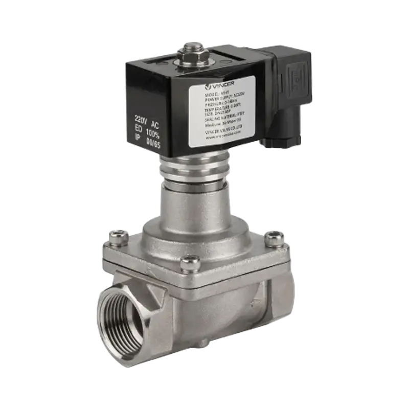
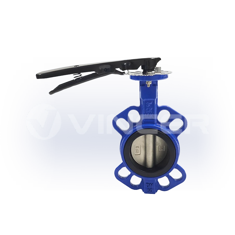
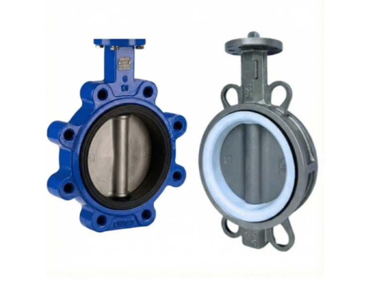
Transfer piping is typically 316L stainless steel or PTFE/PFA-lined for wetted surfaces. Valves follow the same material logic: PFA-lined butterfly valves or ball valves for main switching duties, PTFE diaphragm valves for precision dosing at the filling station, and magnetically driven centrifugal pumps to eliminate mechanical seal leakage points. Sealing materials are limited to FFKM perfluoroelastomer — the only elastomer class that withstands long-term exposure to LiPF₆-containing carbonate solvents without swelling or degrading.
The entire electrolyte handling loop operates inside a dry room with a dew point of -40°C or lower. Moisture sensors monitor the system continuously; an excursion above 20 ppm water in the electrolyte triggers an immediate production hold.
NMP Solvent Recovery — The Recycling Loop That Pays for Itself
NMP is the workhorse solvent of cathode manufacturing, and at coating-line exhaust rates of 200–500 kg per hour, it represents a substantial operating cost. A single coating line running 24/7 evaporates roughly 1,500–4,000 tonnes of NMP per year. At industrial-grade pricing of $2–3/kg, that is $3–12 million annually — vented to atmosphere if no recovery system is in place.
The standard recovery architecture uses a three-stage process. First, a condensation unit recovers 60–70% of the NMP from the hot exhaust stream. Second, a zeolite rotary-wheel adsorber captures most of the remainder, bringing total recovery above 99%. Third, a distillation column purifies the recovered liquid to ≥ 99.9% — electronic-grade NMP ready to be reused in the slurry mixing room. The remaining exhaust, with non-methane hydrocarbon concentration below 50 mg/m³, is compliant with emission standards before release.
All recovery-system piping is SUS304 stainless steel, fully welded and pressure-tested to -3,000 Pa. Proportional control valves regulate chilled-water flow to the condenser stages, magnetic-drive pumps transfer the recovered NMP liquid to storage tanks, and online TVOC sensors monitor return-air concentration at ≤ 6 ppm.
Process Water, Cooling, and Compressed Air — The Unsung Utility Trio
Beyond electrolytes and solvents, three utility systems keep the factory running. Deionized water at ≤ 1 μS/cm conductivity feeds slurry preparation and equipment cleaning, flowing through PP or PVDF piping to prevent metal-ion contamination. Chilled water at 7–12°C removes heat from formation cabinets and drying-oven exhaust streams, circulated through galvanized or stainless steel piping with cast-steel gate or butterfly valves. Compressed air, filtered to a dew point of -40°C and oil content below 0.01 mg/m³, powers pneumatic actuators and instrumentation across the plant.
These three systems are the factory’s circulatory, thermal-regulation, and nervous systems. They run quietly, invisibly — until one stops, and the whole line stops with it.
Quality, Safety, and the Cost of Scale — What Separates Top-Tier from Bottom-Tier Production
In battery manufacturing, quality is not a final checkpoint — it is a cumulative chain. A defect introduced during mixing — an undispersed agglomerate, a moisture ingress — may not surface until formation, ten days and tens of thousands of dollars worth of processing later. That is precisely why 75% of manufacturing findings are discovered at the system integration stage, when recovery is no longer possible.
The quality framework spans three gates. Incoming quality control verifies the batch consistency of every raw material — active material particle size distribution, separator Gurley number and porosity, electrolyte water content and purity. In-process quality control uses in-line β-ray or X-ray gauges for coating areal density, CCD machine-vision systems for electrode surface-defect detection, and weld-strength monitors at every tab-joint station. Outgoing quality control runs the full battery of end-of-line tests covered earlier — capacity, internal resistance, self-discharge rate, X-ray/CT, and helium leak check.
The cell-level defect catalog is sobering: burrs above 15 μm that can pierce separators, metallic contaminant particles above 50 μm that can cause internal shorts, separator pinholes, electrode wrinkles from uneven winding tension, jelly-roll buckling, tab-weld voids, and lithium plating caused by an N/P ratio (negative-to-positive capacity ratio) falling below the safe window of 1.05–1.15. Any one of these, if undetected, can cascade into a field failure — and field failures in lithium-ion batteries are rarely benign.
Safety compliance is governed by a framework of international standards: IEC 62619 for industrial lithium cell safety, IEC 63056 for energy storage system batteries, UL 9540 and UL 1973 for North American stationary and auxiliary-power applications, and UN 38.3 for transport safety certification.
For those planning a production line, the capital cost benchmarks provide sobering context. Total CAPEX for cell manufacturing runs $70–110 million per GWh of annual capacity, rising to $95–150 million per GWh when pack assembly is included (Kearney, 2025). Production equipment consumes 75–80% of that total — with formation/aging alone claiming 15–20%, electrode coating and drying 10–15%, and calendering and slitting another 10–15%. Chinese plants operate at roughly 50–65% of Western CAPEX levels, driven by lower labor costs and a mature domestic equipment supply chain. Labor intensity runs approximately 70 full-time employees per GWh-year of capacity. The minimum viable scale for a new entrant is about 10 GWh of annual capacity; healthy profitability typically requires 15–22 GWh.
These are the numbers that separate a PowerPoint factory from a real one. The manufacturing process described in this article — electrode coating at ±1.5% areal-density tolerance, cell assembly at -60°C dew point, formation cycling over days to build a 20 nm SEI layer — is not a set of aspirational best practices. It is the baseline for producing a cell that will not catch fire, will not degrade prematurely, and will deliver the performance its datasheet promises.
For battery production facilities requiring fluid-handling systems — from PTFE-lined valves for electrolyte distribution to stainless-steel actuated ball valves for NMP recovery loops — manufacturers with deep material customization capabilities can provide chemical-compatibility verification and application-specific valve configurations across multiple international standards.
References
- Kearney. “Powering Through: How EV Battery Producers Can Beat the Cost Crunch.” 2025. kearney.com
- Nature Communications. “Challenges and Opportunities for High-Quality Battery Production at Scale.” 2025. nature.com
- Intertek CEA. “Quality Risks in Energy Storage Manufacturing.” 2025. taiyangnews.info
- Fraunhofer FFB. “Technology Radar — Battery Production.” battery-technology.net
- Thunder Said Energy. “Battery Gigafactory Capex Costs.” thundersaidenergy.com
- Dragonfly Energy. “A Look at the Manufacturing Process of Lithium-Ion Battery Cells.” dragonflyenergy.com
- Cole-Parmer. “Critical Fluid Handling Needs in Lithium-Ion Battery Manufacturing.” coleparmer.ca
- GEMÜ Group. “Engineered GEMÜ Solutions for the Battery Lifecycle.” Valve User Magazine. valveuser.com
- vincervalve.com (Client homepage)