المكونات الأساسية وأشكال الخلايا — ما الذي تتكون منه بطارية ليثيوم أيون؟
تهدف كل خطوة تصنيعية تالية إلى تجميع أربعة مكونات في أحد الأشكال الثلاثة بدقة متناهية. وقبل الخوض في تفاصيل خط الإنتاج، من المفيد أن نعرف ما الذي نقوم بتصنيعه.
تتكون خلية الليثيوم-أيون من أربع طبقات أساسية. إن الكاثود (القطب الموجب) عادةً ما يكون أكسيدًا لمعدن الليثيوم — إما NMC (LiNiₓMnₓCo₁₋₂ₓO₂) الذي يوفر كثافة طاقة أعلى، أو LFP (LiFePO₄) الذي يوفر استقرارًا حراريًا أفضل مع كثافة طاقة أقل بنسبة تتراوح بين 30 و40% تقريبًا. إن الأنود (القطب السالب) يكون دائمًا تقريبًا عبارة عن رقائق نحاسية مغلفة بالجرافيت. ويوجد بينهما طبقة ذات مسام دقيقة فاصل — غشاء من البولي بروبيلين أو البولي إيثيلين لا يتجاوز سمكه 9–25 ميكرومتر، وتبلغ مساميته 40–50% — يمنع التلامس المادي بينما يسمح بمرور أيونات الليثيوم. الـ الشحنة الكهربائية يملأ كل مسام: محلول بتركيز 1.0–1.2 مولار من ملح LiPF₆ مذاب في خليط من الكربونات العضوية (EC، DMC، EMC).
يتم تجميع هذه الطبقات الأربع في أحد التنسيقات الثلاثة للخلايا:
| شكل الجهاز | الهيكل وطريقة التجميع | التطبيقات النموذجية |
|---|---|---|
| أسطواني الشكل | أقطاب كهربائية ملفوفة على شكل “لفافة هلامية”، موضوعة داخل علبة من الفولاذ أو الألومنيوم | الأدوات الكهربائية، وأجهزة الكمبيوتر المحمولة، وسيارات تسلا الكهربائية (18650، 21700، 4680) |
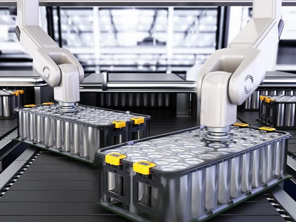
| منشوري الشكل | صفائح أقطاب كهربائية مكدسة أو ملفوفة داخل علبة معدنية صلبة مستطيلة الشكل | السيارات الكهربائية، وأنظمة تخزين الطاقة، والمعدات الصناعية |
| حقيبة صغيرة | طبقات مكدسة أو مطوية على شكل حرف Z ومغلفة داخل غشاء بوليمر مغلف بالألمنيوم | الأجهزة الإلكترونية الاستهلاكية، والأجهزة النحيفة، وبعض وحدات السيارات الكهربائية |
يؤثر اختيار الشكل على كل قرار تصنيعي لاحق — سواء كان ذلك فيما يتعلق باللف مقابل التكديس، أو مادة الغلاف، أو حجم تعبئة الإلكتروليت، أو حتى بروتوكول التشكيل. ولكن بغض النظر عن الشكل النهائي، تتبع عملية الإنتاج نفس التسلسل المكون من ثلاث مراحل: تصنيع الأقطاب الكهربائية، وتجميع الخلايا، وتشطيب الخلايا.
تصنيع الأقطاب الكهربائية — من المسحوق الخام إلى الرقائق المطلية بدقة
يُعد القطب الكهربائي أساس أداء البطارية. فالتوحيد في الطلاء وكثافته وتفاوت سماكته تحدد بشكل مباشر السعة النهائية للخلية ومقاومتها الداخلية وعمرها التشغيلي. ويتمثل التحدي الأساسي الذي يرافق جميع المراحل الخمس لتصنيع الأقطاب الكهربائية في السؤال التالي: كيف يمكن تحقيق دقة على مستوى الميكرون عند سرعات إنتاج تتراوح بين 60 و100 متر في الدقيقة؟
الخلط وتحضير الملاط — الصيغة التي تحدد الأداء
تُعد معجون الكاثود بمثابة «وصفة سرية» في مصانع البطاريات. تتكون التركيبة النموذجية من حوالي 94% من المادة الفعالة (مسحوق NMC أو LFP)، و3% من أسود الكربون الموصّل، و3% من مادة ربط PVDF بالوزن — وكلها مشتتة في مذيب NMP (N-methyl-2-pyrrolidone) لتحقيق لزوجة مستهدفة تتراوح بين 3,000 و8,000 سنتيبواز. يتبع ملاط القطب الموجب منطقًا مشابهًا، لكنه يستخدم مادة نشطة من الجرافيت، ونظام رابط مختلف (عادةً CMC/SBR في الماء)، ويستهدف نطاق لزوجة أقل يتراوح بين 2,000 و4,000 سنتيبواز.
يتم الخلط داخل خلاطات كوكبية أو أجهزة تشتيت عالية السرعة في ظل ظروف تفريغ (≤ -0.09 ميجا باسكال) لإزالة فقاعات الهواء المحبوسة. يجب أن يظل محتوى الماء في مادة NMP أقل من 300 جزء في المليون — فأي رطوبة زائدة تهاجم المادة الرابطة PVDF وتؤدي إلى تدهور استقرار الملاط. يتم فحص الملاط النهائي للتأكد من دقة الجسيمات (≤ 25 ميكرومتر) والمحتوى الصلب (50–70%)، ثم يتم نقله إلى خط الطلاء عبر أنابيب محكمة الإغلاق.
الطلاء — وضع القطب الكهربائي بدقة تصل إلى مستوى الميكرون
يُعد الطلاء مجالًا يلتقي فيه الهندسة الدقيقة مع التصنيع عالي السرعة. يتم تطبيق معجون الكاثود على رقائق الألومنيوم بسمك 12–20 ميكرومتر؛ بينما يتم تطبيق معجون الأنود على رقائق النحاس بسمك 8–12 ميكرومتر. والتقنية السائدة هي الطلاء باستخدام القالب الشقي — وهو رأس بثق دقيق بفجوة شفوية تتراوح بين 100 و300 ميكرومتر، يعمل على وضع طبقة رطبة متصلة بسرعات تتراوح بين 60 و100 متر/دقيقة على خط إنتاج من لفة إلى لفة.
يتراوح سمك الطبقة الجافة المستهدف بين 50 و150 ميكرومترًا للكاثود وبين 50 و100 ميكرومترًا للأنود، مع تفاوت في الكثافة المساحية يبلغ ±1.5%. ويظهر أي انحراف لاحقًا في شكل تباين في السعة بين الخلايا. وتحمل عيوب الطلاء الشائعة — مثل الثقوب الدقيقة، والملمس الشبيه بقشر البرتقال، والخطوط الطولية، وسماكة الحواف — كل منها علامة فشل مميزة: فالثقوب الدقيقة تخلق نقاط سخونة محلية، وتؤدي حبيبات الحواف إلى اختلال محاذاة التكديس في المراحل اللاحقة، بينما تنتج الخطوط الطولية توزيعًا غير متساوٍ للتيار أثناء الدورات.
التجفيف — إزالة المذيب دون إحداث تشققات في القطب الكهربائي
عندما تخرج الرقاقة المطلية من رأس القالب الشقي، تدخل إلى فرن تجفيف متعدد المناطق. ترتفع درجة الحرارة تدريجيًا عبر ثلاث مناطق — تتراوح تقريبًا بين 50 و80 درجة مئوية، ثم بين 100 و120 درجة مئوية، ثم بين 130 و150 درجة مئوية — لتطرد مذيب NMP دون التسبب في انتقال المادة الرابطة. فإذا جُففت بسرعة كبيرة، يتشكل قشرة على السطح، مما يحبس المذيب في الداخل ويؤدي إلى تشكل شقوق عندما يتسرب المذيب في النهاية. أما إذا جُففت ببطء شديد، تنخفض سرعة خط الإنتاج إلى ما دون مستوى الربحية.
يجب أن تنخفض الرطوبة المتبقية بعد التجفيف إلى أقل من 500 جزء في المليون. وفي الوقت نفسه، يتم تجميع مادة NMP المتبخرة — التي تتراوح بين 200 و500 كجم في الساعة من خط طلاء واحد — وتوجيهها إلى نظام استرداد المذيبات. وبسعر NMP الصناعي الذي يتراوح بين $2 و3/كجم، فإن أي خط طلاء يقوم بتصريف المذيب في الغلاف الجوي يكبد خسارة تزيد عن ألف دولار في الساعة.
التكوي — ضغط القطب الكهربائي حتى الوصول إلى الكثافة المثالية
يمر القطب الكهربائي المجفف عبر زوج من الأسطوانات الثقيلة التي تمارس ضغطًا خطيًّا يتراوح بين 50 و100 نيوتن/مم. تعمل خطوة الكالندر هذه على سحق الطبقة المسامية حتى تصل إلى الكثافة المستهدفة: 3.4–3.8 غ/سم³ للكاثودات من مركب النيكلس-المغنيسيوم-الكابليوم (NMC) و1.4–1.7 غ/سم³ للأنودات الجرافيتية، مما يترك مسامية تتراوح بين 25–35% (الكاثود) و30–40% (الأنود).
هذه هي المقايضة المباشرة بين كثافة الطاقة وقدرة التيار. فكلما زادت درجة الضغط، زادت كمية المادة الفعالة المعبأة في نفس الحجم — مما يرفع كثافة الطاقة — ولكنه يؤدي في الوقت نفسه إلى إغلاق القنوات المسامية التي تحتاج أيونات الليثيوم للمرور عبرها، مما يقلل من قدرة التيار. ويؤكد ارتداد السماكة إلى ما أقل من 5% بعد عملية الكالندرة أن القطب الكهربائي قد تم ضغطه إلى حالة مستقرة.
التقطيع والقطع — تشكيل الأقطاب الكهربائية للخلية النهائية
يتم تقطيع “اللفافة الأم” المكبسّة طوليًا إلى لفائف فرعية أضيق، ثم يتم قصها باستخدام قوالب أو بالليزر إلى صفائح أقطاب كهربائية فردية بحجم يتناسب مع شكل الخلية المستهدفة. ويبلغ التفاوت المسموح به في الأبعاد ±0.1 مم. ويكمن الخطر الخفي هنا في وجود النتوءات — وهي شظايا معدنية على حافة القطع. وإذا تجاوزت الحواف الخشنة 15 ميكرومتر (ما يعادل تقريبًا خمس قطر شعرة الإنسان)، فإنها قد تخترق الفاصل أثناء التجميع وتسبب قصرًا داخليًا في الدائرة الكهربائية. وهذا يمثل أول بوابة أمان مادية في خط الإنتاج.
ثم تُدخل الأقطاب المقطوعة إلى فرن تفريغ هوائي عند درجة حرارة تتراوح بين 80 و110 درجة مئوية لمدة تتراوح بين 6 و24 ساعة، مما يؤدي إلى خفض الرطوبة المتبقية إلى أقل من 100 جزء في المليون قبل نقلها إلى غرفة التجفيف لتجميعها.
3,000–8,000 cP
50–150 ميكرومتر من الطبقة الجافة
المياه المتبقية (H₂O) <500 جزء في المليون
3.4–3.8 غ/سم³ (NMC)
Burr control <15 μm
Cell Assembly — Building the Electrochemical Heart
Lithium-ion cell assembly takes place in dry rooms with dew points as low as -60°C — drier than the Sahara Desert by orders of magnitude. The reason is unforgiving chemistry: any moisture that enters the cell during assembly reacts with LiPF₆ electrolyte to form hydrofluoric acid (HF), which attacks the cathode and releases oxygen, setting the stage for thermal runaway.
Winding vs. Stacking — Two Philosophies of Electrode Assembly
The prepared anode, separator, and cathode sheets must now be combined into a cell. Two competing philosophies govern this step.
اللف rolls the three layers into a cylindrical or flattened “jelly roll” at speeds of 2–4 seconds per 18650-sized cell. Tension control is the critical variable — ±0.1 N precision keeps the layers aligned within 0.3 mm. Winding is fast, mature, and well-suited to cylindrical formats.
التكديس lays individual electrode sheets and separator layers in alternating sequence — either Z-folded from a continuous separator roll or assembled as discrete sheets. Alignment tolerance tightens to ±0.2 mm, and the process is inherently slower than winding. But stacking achieves 3–5% higher space utilization inside prismatic and pouch cells, and the uniform layer pressure produces lower internal resistance.
The trade-off table looks like this:
| البعد | اللف | التكديس |
|---|---|---|
| Best format | Cylindrical, some prismatic | Prismatic, pouch |
| Production speed | 2–4 sec/cell (18650) | Slower (discrete steps) |
| الاستفادة من المساحة | الخط الأساسي | +3–5% |
| المقاومة الداخلية | Slightly higher (curved layers) | Lower (flat, uniform pressure) |
| Equipment cost | أدنى | أعلى |
Electrolyte Filling — The Most Delicate Step in Assembly
The assembled but unsealed cell is moved into a vacuum chamber, evacuated to an absolute pressure below 10 kPa, and then filled with electrolyte. The fill volume is calculated precisely — the cell’s internal pore volume multiplied by a 5–15% excess coefficient to ensure complete wetting — and dosed to ±0.5 g accuracy.
After filling, the cell rests for 4–24 hours under vacuum to allow capillary wetting of every pore. The electrolyte itself is more than just LiPF₆ salt in solvent: functional additives like vinylene carbonate (VC, 1–3%) and fluoroethylene carbonate (FEC, 2–5%) are blended in to promote stable SEI formation during the next stage.
Encasement and Sealing — Locking the Cell for Life
Metal-can cells (cylindrical and prismatic) are sealed by laser-welding the cap to the can body, then checked with helium leak detection — the acceptance standard is a leak rate below 1×10⁻⁹ Pa·m³/s. Pouch cells are heat-sealed on three sides before filling, then vacuum-sealed on the fourth side after electrolyte wetting, with a peel strength exceeding 35 N per 15 mm of seal width to guarantee integrity over a decade or more of service.
Formation, Aging, and End-of-Line Testing — Where the Battery Learns to Be a Battery
Formation is the single most expensive non-materials step in battery manufacturing. It accounts for roughly 15–20% of total production equipment CAPEX and can take days to weeks. No factory skips or shortens it — because this is where the cell builds its fundamental safety architecture.
During the first charge, at a gentle current of 0.05–0.2C, the electrolyte decomposes in a controlled way at the anode surface, forming a 20–50 nm layer called the solid electrolyte interphase (SEI). A well-formed SEI is electronically insulating but ionically conductive — it passivates the anode, prevents further electrolyte decomposition, and enables stable cycling for thousands of charge-discharge cycles. The cost of this protection is a 5–10% irreversible loss of first-cycle lithium, consumed in building the SEI.
Gases generated during formation (H₂, C₂H₄, CO₂) are vented before final sealing. The cell then enters aging: 3–21 days at 30–50°C, during which the SEI stabilizes and the electrolyte fully equilibrates. Self-discharge monitoring during aging identifies defective cells — a voltage drop exceeding 0.03 mV per day flags a potential internal short or contamination issue.
Every cell leaving the line then undergoes end-of-line testing: capacity verification (±2% of nominal), AC internal resistance at 1 kHz, and X-ray or CT scanning to detect internal metallic particles above 50 μm or electrode misalignment. Cells are graded by performance — A-grade cells proceed to module and pack assembly, B-grade cells are diverted to less demanding applications like stationary energy storage, and C-grade cells are scrapped.
A 2025 review in Nature Communications noted that ensuring consistent quality at the scale of modern gigafactories — where a single 38 GWh/year plant produces nearly 70 cells per second — “is perhaps the most important technical challenge hindering the ability to rapidly ramp battery production.” That challenge is compounded by the fact that, according to a 2025 Intertek CEA audit of battery manufacturing quality, approximately 75% of manufacturing findings occur at the system integration level — after individual cells have already passed their tests, when the cost of rejection is highest.
Fluid Handling and Process Utilities — The Overlooked Backbone of Battery Production
Every major process stage discussed so far depends on fluids. Electrolytes, solvents, process water, coolants, compressed air — each flows through pipes, valves, and pumps that rarely appear in manufacturing overviews. That silence is costly. Fluid system failures rank among the most common causes of factory downtime and product quality issues, yet they are the last thing most production-line planners investigate when something goes wrong.
Electrolyte and Chemical Handling — Precision Under Hazardous Conditions
LiPF₆ electrolyte is one of the most demanding chemicals in the battery plant. It reacts violently with moisture to form HF — a chemical that etches glass and attacks metal. It is flammable. Its decomposition products corrode standard stainless steel. Handling it requires a fully closed system.
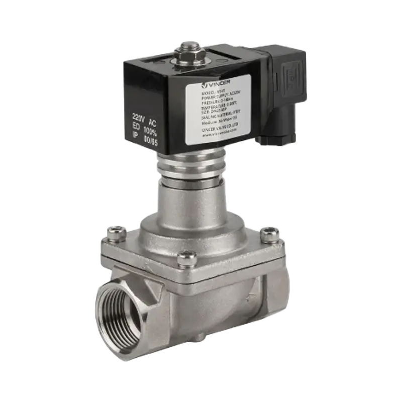
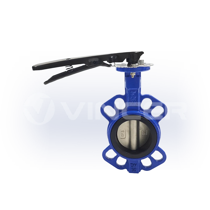
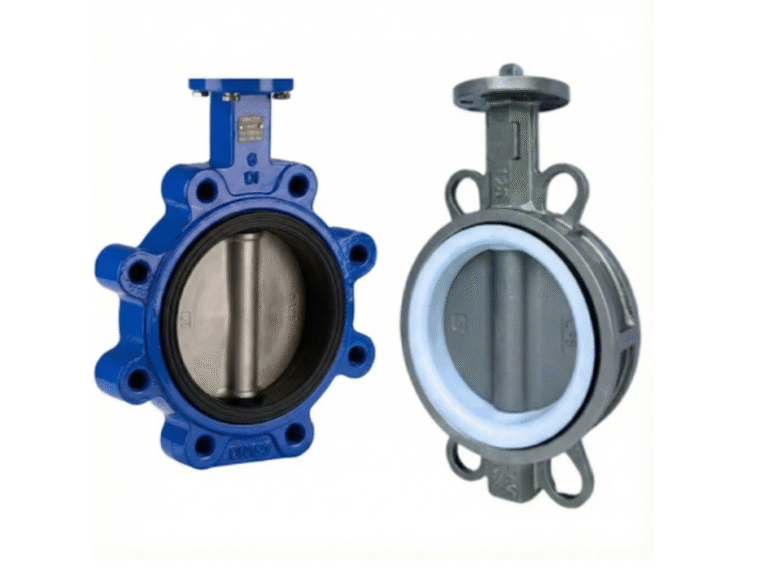
Transfer piping is typically 316L stainless steel or PTFE/PFA-lined for wetted surfaces. Valves follow the same material logic: PFA-lined butterfly valves or ball valves for main switching duties, PTFE diaphragm valves for precision dosing at the filling station, and magnetically driven centrifugal pumps to eliminate mechanical seal leakage points. Sealing materials are limited to FFKM perfluoroelastomer — the only elastomer class that withstands long-term exposure to LiPF₆-containing carbonate solvents without swelling or degrading.
The entire electrolyte handling loop operates inside a dry room with a dew point of -40°C or lower. Moisture sensors monitor the system continuously; an excursion above 20 ppm water in the electrolyte triggers an immediate production hold.
NMP Solvent Recovery — The Recycling Loop That Pays for Itself
NMP is the workhorse solvent of cathode manufacturing, and at coating-line exhaust rates of 200–500 kg per hour, it represents a substantial operating cost. A single coating line running 24/7 evaporates roughly 1,500–4,000 tonnes of NMP per year. At industrial-grade pricing of $2–3/kg, that is $3–12 million annually — vented to atmosphere if no recovery system is in place.
The standard recovery architecture uses a three-stage process. First, a condensation unit recovers 60–70% of the NMP from the hot exhaust stream. Second, a zeolite rotary-wheel adsorber captures most of the remainder, bringing total recovery above 99%. Third, a distillation column purifies the recovered liquid to ≥ 99.9% — electronic-grade NMP ready to be reused in the slurry mixing room. The remaining exhaust, with non-methane hydrocarbon concentration below 50 mg/m³, is compliant with emission standards before release.
All recovery-system piping is SUS304 stainless steel, fully welded and pressure-tested to -3,000 Pa. Proportional control valves regulate chilled-water flow to the condenser stages, magnetic-drive pumps transfer the recovered NMP liquid to storage tanks, and online TVOC sensors monitor return-air concentration at ≤ 6 ppm.
Process Water, Cooling, and Compressed Air — The Unsung Utility Trio
Beyond electrolytes and solvents, three utility systems keep the factory running. Deionized water at ≤ 1 μS/cm conductivity feeds slurry preparation and equipment cleaning, flowing through PP or PVDF piping to prevent metal-ion contamination. Chilled water at 7–12°C removes heat from formation cabinets and drying-oven exhaust streams, circulated through galvanized or stainless steel piping with cast-steel gate or butterfly valves. الهواء المضغوط, filtered to a dew point of -40°C and oil content below 0.01 mg/m³, powers pneumatic actuators and instrumentation across the plant.
These three systems are the factory’s circulatory, thermal-regulation, and nervous systems. They run quietly, invisibly — until one stops, and the whole line stops with it.
Quality, Safety, and the Cost of Scale — What Separates Top-Tier from Bottom-Tier Production
In battery manufacturing, quality is not a final checkpoint — it is a cumulative chain. A defect introduced during mixing — an undispersed agglomerate, a moisture ingress — may not surface until formation, ten days and tens of thousands of dollars worth of processing later. That is precisely why 75% of manufacturing findings are discovered at the system integration stage, when recovery is no longer possible.
The quality framework spans three gates. Incoming quality control verifies the batch consistency of every raw material — active material particle size distribution, separator Gurley number and porosity, electrolyte water content and purity. In-process quality control uses in-line β-ray or X-ray gauges for coating areal density, CCD machine-vision systems for electrode surface-defect detection, and weld-strength monitors at every tab-joint station. Outgoing quality control runs the full battery of end-of-line tests covered earlier — capacity, internal resistance, self-discharge rate, X-ray/CT, and helium leak check.
The cell-level defect catalog is sobering: burrs above 15 μm that can pierce separators, metallic contaminant particles above 50 μm that can cause internal shorts, separator pinholes, electrode wrinkles from uneven winding tension, jelly-roll buckling, tab-weld voids, and lithium plating caused by an N/P ratio (negative-to-positive capacity ratio) falling below the safe window of 1.05–1.15. Any one of these, if undetected, can cascade into a field failure — and field failures in lithium-ion batteries are rarely benign.
Safety compliance is governed by a framework of international standards: IEC 62619 for industrial lithium cell safety, IEC 63056 for energy storage system batteries, UL 9540 و UL 1973 for North American stationary and auxiliary-power applications, and UN 38.3 for transport safety certification.
For those planning a production line, the capital cost benchmarks provide sobering context. Total CAPEX for cell manufacturing runs $70–110 million per GWh of annual capacity, rising to $95–150 million per GWh when pack assembly is included (Kearney, 2025). Production equipment consumes 75–80% of that total — with formation/aging alone claiming 15–20%, electrode coating and drying 10–15%, and calendering and slitting another 10–15%. Chinese plants operate at roughly 50–65% of Western CAPEX levels, driven by lower labor costs and a mature domestic equipment supply chain. Labor intensity runs approximately 70 full-time employees per GWh-year of capacity. The minimum viable scale for a new entrant is about 10 GWh of annual capacity; healthy profitability typically requires 15–22 GWh.
These are the numbers that separate a PowerPoint factory from a real one. The manufacturing process described in this article — electrode coating at ±1.5% areal-density tolerance, cell assembly at -60°C dew point, formation cycling over days to build a 20 nm SEI layer — is not a set of aspirational best practices. It is the baseline for producing a cell that will not catch fire, will not degrade prematurely, and will deliver the performance its datasheet promises.
For battery production facilities requiring fluid-handling systems — from PTFE-lined valves for electrolyte distribution to stainless-steel actuated ball valves for NMP recovery loops — manufacturers with deep material customization capabilities can provide chemical-compatibility verification and application-specific valve configurations across multiple international standards.
المراجع
- Kearney. “Powering Through: How EV Battery Producers Can Beat the Cost Crunch.” 2025. kearney.com
- Nature Communications. “Challenges and Opportunities for High-Quality Battery Production at Scale.” 2025. nature.com
- Intertek CEA. “Quality Risks in Energy Storage Manufacturing.” 2025. taiyangnews.info
- Fraunhofer FFB. “Technology Radar — Battery Production.” battery-technology.net
- Thunder Said Energy. “Battery Gigafactory Capex Costs.” thundersaidenergy.com
- Dragonfly Energy. “A Look at the Manufacturing Process of Lithium-Ion Battery Cells.” dragonflyenergy.com
- Cole-Parmer. “Critical Fluid Handling Needs in Lithium-Ion Battery Manufacturing.” coleparmer.ca
- GEMÜ Group. “Engineered GEMÜ Solutions for the Battery Lifecycle.” Valve User Magazine. valveuser.com
- vincervalve.com (Client homepage)