خطة هندسية لهيكل النظام، ومطابقة المواد، والموثوقية
التكاليف الخفية لشبكات السوائل المجزأة
تكشف بيانات القطاع عن حقيقة تتعارض مع الفطرة السليمة في مجال التصنيع الحديث: فالغالبية العظمى من الأعطال الكارثية في أنظمة السوائل الصناعية — وما يترتب عليها من خسائر بملايين الدولارات جراء فترات التوقف غير المخطط لها — لا تنجم عن عيوب في تصنيع الأجزاء الفردية. بل تنشأ، بدلاً من ذلك، عن عدم توافق جوهري في التصميم والمواصفات. وعندما يكتفي مهندسو العمليات بتجميع المكونات المنفصلة بدلاً من وضع استراتيجية متماسكة ومبنية على أسس علمية لديناميكيات السوائل، تظل الخسائر المالية غير مرئية تمامًا إلى أن يتوقف خط الأنابيب عن العمل بشكل غير متوقع.
بالنسبة لمديري المصانع ومديري الأتمتة وقادة المشتريات، فإن الرهان هنا ثنائي. فإما أن تقوموا بتصميم نظام «قلب وأوعية دموية» مرن لمنشأتكم، أو أنكم، دون قصد، تضعون العد التنازلي لحدوث التسرب الخطير التالي. تتخلص هذه الخطة الشاملة من النصائح العامة ذات المستوى العالي لتقدم إطارًا هندسيًّا متينًا: كيفية إتقان ريولوجيا السوائل المعقدة، وتحديد حجم المضخات باستخدام حسابات هيدروليكية دقيقة، وفهم علم المعادن المعقد لصمامات التحكم، والتخفيف الدقيق من النفقات التشغيلية الخفية (OPEX) التي تزيد باستمرار من إجمالي تكلفة الملكية (TCO).
التحول النوعي: من المكونات المنفصلة إلى الحلول المتكاملة لمعالجة السوائل
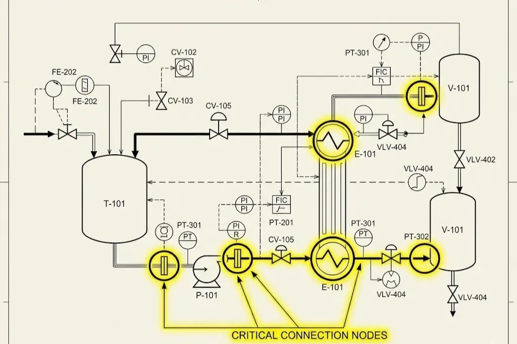
على مدى عقود، ساد نهج شديد التجزئة في مجال المشتريات الصناعية. فمهندسو التصميم كانوا يشترون مضخة طرد مركزي عالية الكفاءة من مورد واحد، وأجهزة آلية صمامات معالجة السوائل من مصدر آخر، وشبكات الأنابيب من مصدر ثالث، انطلاقًا من افتراض أن تجميع مكونات من الدرجة الأولى سيؤدي بطبيعة الحال إلى شبكة وظيفية من الدرجة الأولى. وغالبًا ما تؤدي هذه العقلية البالية إلى ما يسميه المهندسون المخضرمون “عنق الزجاجة في النظام”. فموثوقية منشأة المعالجة لا تتجاوز موثوقية أضعف نقطة توصيل فيها وأقلها مواصفات.
لنأخذ التشبيه الوعائي في الاعتبار. قد يكون لديك قلب قوي بشكل ملحوظ (المضخة)، ولكن إذا كانت شرايينك (الهيكل المعدني للأنابيب) مصابة بتكلس شديد أو إذا فشلت صمامات قلبك في تنظيم الضغط بدقة، فإن النظام البيولوجي بأكمله يواجه انهيارًا وشيكًا. في السياق الصناعي، سيؤدي استخدام مضخة عالية السعة إلى جانب صمام آلي صغير الحجم أو بطيء الاستجابة حتمًا إلى حدوث صدمة مائية شديدة. وفقًا لمعادلة جوكوفسكي، يمكن لموجات الصدمة الحركية المفاجئة الناتجة عن الإغلاق السريع للصمام أن ترفع ضغوط الأنابيب الداخلية بمقدار مئات PSI في أجزاء من الألف من الثانية. يمكن لهذه الظواهر الهيدروليكية العابرة أن تمزق دعامات الأنابيب الفولاذية من الجدران الخرسانية، وتحطم الأختام الميكانيكية باهظة الثمن، وتمزق خطوط الأجهزة الحساسة.
لذلك، فإن الحديثة حلول معالجة السوائل لا تُحدد هذه الخصائص من خلال المواصفات الفيزيائية الفردية المطبوعة في ورقة بيانات منتج واحد. بل تُحدد من خلال التفاعل السلس والتآزري بين جميع مكونات بنية التحكم ذات الحلقة المغلقة. ويؤدي تبني هذا النموذج المتكامل إلى تحويل التركيز الهندسي من مجرد “نقل السوائل” إلى تنظيم بيئة لنقل السوائل تتسم بدرجة عالية من التحكم والقدرة على التنبؤ والأمان.
فك رموز ديناميكا الموائع: المخطط التوجيهي لاختيار المعدات
قبل تحديد أي معدات، أو إنجاز رسومات CAD، أو توقيع أوامر الشراء، يجب أن يتمتع المهندس بفهم دقيق على المستوى الجزيئي للمواد التي يتم نقلها. ولا يتم اختيار المعدات أبدًا بناءً على الميزانية الرأسمالية المتاحة وحدها؛ بل يخضع اختيارها بالكامل لـ“خصائص” السوائل المستخدمة في العملية من الناحية الفيزيائية والكيميائية والحرارية. ويُعد عدم مراعاة القوانين الثابتة لديناميكا الموائع السبب الجذري لتدهور الأصول قبل الأوان.
التعامل مع السوائل عالية اللزوجة والحساسة للقص
اللزوجة — وهي مقياس المقاومة الداخلية للسائل للتشوه التدريجي الناتج عن إجهاد القص أو إجهاد الشد — تُغيّر بشكل جذري الطريقة التي معدات معالجة السوائل يجب تصميمها هندسيًا. فمع زيادة اللزوجة الديناميكية، يرتفع الاحتكاك الداخلي داخل السائل بشكل هائل. ويؤدي هذا التغيير الجوهري إلى تغيير رقم رينولدز للنظام، مما يدفع تدفق السائل من حالة اضطرابية فوضوية إلى حالة انسيابية يمكن التنبؤ بها بدرجة عالية، لكنها صعبة الحركة للغاية. وفي أنظمة التدفق الانسيابي، تصبح قوى الطرد المركزي القياسية غير فعالة إلى حد كبير، حيث تحول الطاقة المدخلة إلى حرارة مدمرة بدلاً من حركة حركية.
علاوة على ذلك، تُظهر العديد من الوسائط الصناعية المعقدة سلوكيات غير نيوتونية. الانسيابية الناتجة عن القص تقل لزوجة السوائل (الزائفة اللزوجة)، مثل الكاتشب، أو البوليمرات المنصهرة، أو بعض أنواع الدهانات الصناعية، تحت تأثير الإجهاد الميكانيكي. وعلى العكس من ذلك،, الزيادة في اللزوجة تحت تأثير القص تصبح السوائل (المتوسعة)، مثل المعلقات المركزة من نشا الذرة أو الملاط الكيميائي المحدد، شبه صلبة عند تعريضها للاهتزاز. وإذا قام مدير المصنع بتركيب مضخة ذات دافع عالي السرعة دون تروٍ لنقل المستحلبات الحساسة للقص — مثل الكريمات التجميلية الفاخرة، أو البروتينات الصيدلانية الحيوية الحساسة، أو المضافات الغذائية المعقدة — فإن الاهتزاز الميكانيكي المفرط سيؤدي إلى تدمير البنية الجزيئية للدفعة بشكل دائم. ويؤدي ذلك إلى فصل المنتج بشكل لا رجعة فيه، وخسارة هائلة في العائد، وإتلاف عمليات الإنتاج.
التغلب على الوسائط العدوانية والمسببة للتآكل والكاشطة
عند الهندسة معالجة السوائل الصناعية في أنظمة المعالجة الكيميائية، أو تصنيع أشباه الموصلات، أو قطاعات بطاريات المركبات الكهربائية (EV) الحديثة، فإن العدو الرئيسي هو التدهور الحاد للمواد. ويُعد استخدام الفولاذ المقاوم للصدأ القياسي 316L في بيئة عالية الكلوريد أو في خطوط نقل حمض الهيدروكلوريك المركز خطأً هندسيًّا مكلفًا؛ حيث سيؤدي التآكل النقطي المجهري والتشقق الناتج عن التآكل تحت الإجهاد (SCC) إلى الإخلال بسرعة بالسلامة الهيكلية للأنابيب، مما يؤدي إلى حدوث تسربات بيئية خطيرة. بالإضافة إلى ذلك، يؤدي إدخال سوائل شديدة البرودة إلى خطوط الأنابيب الساخنة إلى حدوث الصدمة الحرارية, ، مما يستلزم حلولًا متطورة لتعويض الإجهاد الميكانيكي، مثل وصلات التمدد المعدنية المموجة التي يتم دمجها مباشرةً في شبكة الأنابيب.
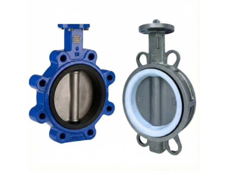
لمكافحة الهجمات الكيميائية البحتة، تستفيد التصميمات الهندسية المتطورة من البوليمرات الفلورية المتقدمة. توفر الصمامات المبطنة بالكامل بـ PTFE (بولي تترافلوروإيثيلين) أو PFA خمولًا كيميائيًا شبه كلي، مما يحمي الهيكل المعدني الخارجي من المواد المسببة للتآكل. ومع ذلك، فمن الحقائق الصناعية الموثقة جيدًا أن المكونات القياسية المبطنة بالفلور تُظهر مقاومة ميكانيكية ضعيفة للغاية للتآكل. وإذا كانت المادة المسببة للتآكل تحتوي أيضًا على جسيمات صلبة كاشطة — مثل ملاط الليثيوم، أو ثاني أكسيد التيتانيوم، أو مخلفات التعدين — فإن البطانة القياسية من مادة PTFE ستتمزق بسرعة بفعل الجسيمات الصلبة عالية السرعة.
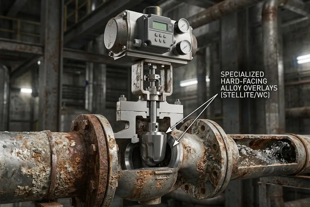
في هذه البيئات التي تنطوي على تهديد مزدوج (تآكل شديد بالإضافة إلى احتكاك شديد)، يتجه الحل الأمثل بعيدًا عن البطانات البوليمرية اللينة. يجب على المهندسين تحديد مكونات سيراميكية هيكلية مصممة خصيصًا، أو استخدام طبقات من السبائك الصلبة — مثل اللحام بالستيليت أو طلاءات كربيد التنغستن — على الحواف والمقاعد المعدنية. ورغم أن تحديد هذه المواد بدقة — الذي قد يبدو أكثر تعقيدًا في البداية — إلا أنه يطيل دورة حياة الأصول بمضاعفات هائلة مقارنة بالبدائل العامة، مما يضمن الاستقرار التشغيلي على المدى الطويل.
جوهر النظام: التقنيات المتطورة للمضخات ومنطق تحديد الحجم
تُعد المضخة المحرك الحركي الرئيسي للعملية برمتها. ومع ذلك، فإن تحديد مواصفات المضخة يمثل عملية حسابية معقدة تتطلب تحليلاً حسابياً متعمقاً لشبكة الأنابيب بأكملها. والانتقال من مبادئ الفيزياء الأساسية إلى المنطق الهندسي القابل للتطبيق يتطلب التعامل مع معلمات هيدروليكية معقدة لضمان تحقيق أقصى قدر من الكفاءة، ومعدلات تدفق مثالية، وإطالة عمر المعدات.
المضخات الطردية مقابل المضخات ذات الإزاحة الإيجابية (PD): القاعدة الذهبية
يكمن الاختلاف الأساسي في اختيار المضخات بين تصميمي المضخات الطردية (PD) والمضخات الطردية المركزية. وتفرض القاعدة الهندسية الذهبية اتباع شجرة قرار محددة للغاية. فإذا كان التطبيق يتطلب نقل كميات كبيرة من السوائل منخفضة اللزوجة عند ضغوط منخفضة نسبيًا ومستقرة، فإن المضخة الطردية المركزية هي الخيار الأمثل. تعتمد المضخات الطردية المركزية على الطاقة الحركية الدورانية، حيث تنقل الزخم إلى السائل عبر دافع دوار. وعلى العكس من ذلك، إذا كانت العملية تتطلب تدفقًا دقيقًا ومقيسًا للمواد عالية اللزوجة في ظل ضغوط نظام متغيرة أو عالية للغاية، فإن استخدام مضخة الإزاحة الإيجابية (مثل المضخة ذات الفصوص الدوارة، أو المضخة ذات التروس الداخلية، أو المضخة ذات التجويف التقدمي) يكون إلزاميًا تمامًا.
يُعد اختيار مضخات طرد مركزي ذات أحجام أكبر من اللازم، انطلاقًا من افتراض أن القوة الحصانية الأعلى تعني تلقائيًا أداءً أفضل، خطأً كلاسيكيًا ومكلفًا يرتكبه المبتدئون. وهذا يخالف المفهوم الأساسي لـ«نقطة الكفاءة المثلى» (BEP). إن إجبار مضخة طرد مركزي على العمل بشكل مستمر في أقصى يسار أو يمين منحنى أدائها المصمم يؤدي إلى دفع شعاعي شديد. وهذه القوة الهيدروليكية غير المتوازنة تؤدي إلى انحراف عمود المضخة، مما يؤدي إلى تلف الأختام الميكانيكية وفشل المحامل قبل الأوان. يجب على المهندسين استخدام قوانين التناسب لحساب تأثير التغيرات في قطر المكره أو سرعة الدوران على معدل التدفق، وضغط الرأس، واستهلاك الطاقة الإجمالي بدقة.
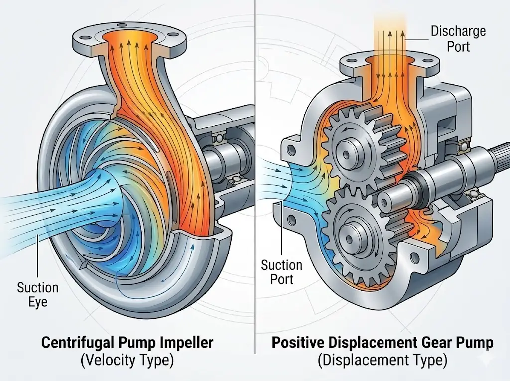
القاتل الخفي: توضيح مفهوم التكهف و NPSH
حتى المضخات التي تم تحديد مواصفاتها وتصنيعها بشكل مثالي يمكن أن تتلف في غضون أسابيع إذا كان التصميم الهيدروليكي لجانب الشفط في المنشأة سيئًا. التكهف هو القاتل الصامت الذي لا يرحم لشبكات السوائل. وفقًا لمبدأ برنولي، يحدث التكهف عندما ينخفض الضغط المطلق للسائل عند عين دوار المضخة إلى ما دون ضغط البخار النوعي للسائل عند درجة حرارة التشغيل تلك.
عندما يحدث هذا الانخفاض الموضعي في الضغط، يغلي السائل على الفور، مكونًا فقاعات بخار مجهرية. ومع انتقال هذه الفقاعات إلى المناطق ذات الضغط الأعلى داخل الحلزون المضخة، فإنها لا تستطيع الحفاظ على حالتها الغازية فتنفجر داخليًّا بعنف. بالنسبة للمشغل الذي يتجول في أرضية المصنع، يبدو صوت التكهف النشط تمامًا كصوت ضخ الحصى أو الكرات الزجاجية عبر أنبوب فولاذي. أما بالنسبة للمعدات نفسها، فيعمل هذا التكهف كمتفجرات مجهرية، حيث يتسبب في إحداث ثقوب وتآكل سريعين، ويؤدي في النهاية إلى تدمير الدوافع المعدنية الصلبة.
المعادلة الهيدروليكية الأساسية
لمنع حدوث التجويف بشكل نهائي، يجب أن يلتزم التصميم الهندسي بصرامة بحسابات «ارتفاع الشفط الإيجابي الصافي» (NPSH). والقاعدة الثابتة هي:
NPSHa > NPSHr + 0.5 م (هامش أمان)
ارتفاع الشفط الإيجابي الصافي المتاح (NPSHa), ، والتي يتحدد مقدارها بناءً على الضغط الجوي ودرجة حرارة السائل والاحتكاك في أنابيب الشفط، يجب أن تتجاوز دائمًا وبفارق كافٍ الارتفاع الإيجابي الصافي المطلوب للشفط (NPSHr) وفقًا لبيانات الاختبارات الصارمة التي أجرتها الشركة المصنعة للمضخة.
الدقة والعزل: تصميم الصمامات والأنابيب ووسائل الإحكام
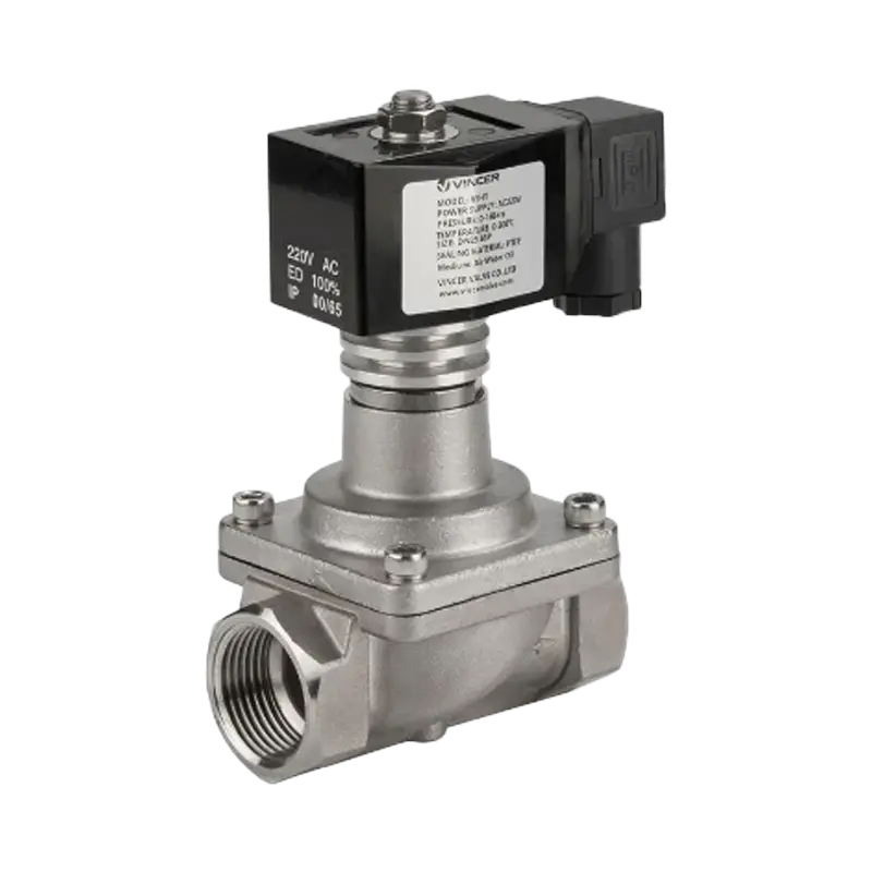
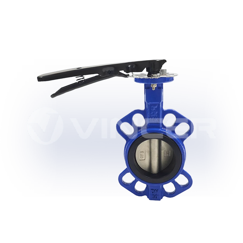
في حين توفر المضخة الطاقة الحركية الخام، فإن الذكاء والأمان والدقة القصوى لأي نظام لمعالجة السوائل تكمن بالكامل في مكوناته الطرفية. فالصمامات هي العناصر المادية المسؤولة عن تنفيذ استراتيجية التحكم الخاصة بك. ويتطلب تحديد مواصفات صمامات التحكم دراسة متعمقة لخصائص التدفق الهوائي والهيدروديناميكي. يجب على المهندسين تحديد بدقة ما إذا كانت العملية تتطلب التدفق الخطي لصمام كروي، أو العزل السريع بربع دورة لصمام كروي مثبت على محور، أو الخنق عالي السعة بنسبة متساوية لصمام فراشة ثلاثي الإزاحة. فصمام التحكم ذو الحجم غير الصحيح — مثل الصمام الذي يعمل باستمرار عند أقل من 10% من شوطه — سيعاني من سحب سلكي شديد (تآكل تآكلي في المقعد) وتحكم غير منتظم في التدفق.
علاوة على ذلك، يجب أن تتوافق آليات الإحكام — ولا سيما حشية الإحكام وموانع تسرب الجذع — بشكل صارم مع أحدث معايير الانبعاثات المتسربة المنخفضة، مثل API 624 أو API 641. وتضمن بروتوكولات الاختبار الصارمة هذه عدم تسرب المركبات العضوية المتطايرة (VOCs) الخطرة وغازات الدفيئة إلى الغلاف الجوي أثناء العمليات الميكانيكية عالية الدورات، مما يحمي الموظفين ويضمن امتثال الشركة للمعايير البيئية.
The Objective 8-Dimensional Analysis Framework
Valve misapplication is the leading cause of fugitive emissions, jammed pneumatic actuators, and premature stem wear. To mathematically eliminate this engineering risk, top-tier system integrators utilize a rigorous 8-Dimensional Analysis Framework prior to finalizing any equipment selection. This methodology cross-examines:
- Medium Composition: pH levels, solid particulate concentration, and specific phase state.
- Operating Temperature: Continuous operating temps, peak spikes, and thermal shock parameters.
- System Pressure: Dynamic flow pressure drops (ΔP) and maximum static shut-off pressure.
- Connection Standards: Flanged (ANSI/DIN/JIS), fully welded, or threaded.
- Control Method: Pneumatic, electric, or modulating with smart positioners.
- Body and Trim Material: Precise metallurgy for the shell and specific elastomers for seating.
- Industry-Specific Certifications: FDA, API, ATEX, SIL requirements.
- Physical Installation Space: Envelope constraints and maintenance accessibility.
For instance, when processing 170°C heat transfer fluids (thermal oil), a novice might specify a standard ball valve with RPTFE soft seats. Under continuous thermal cycling, the RPTFE will rapidly degrade, extrude, and leak. Applying this 8-dimensional matrix instantly flags the thermal shock and extrusion risk, directly specifying a bellows seal globe valve or a metal-seated ball valve with live-loaded graphite packing. This surgical precision in component matching mitigates the vast majority of downstream leakage and emergency maintenance contingencies.
The Smart Factory Era: IoT Integration and Automated Fluid Control
The era of Industry 4.0 has elevated plant safety and efficiency from passive mechanical boundaries (relying solely on thicker steel) to active, intelligent, and digital monitoring. Legacy fluid systems act as silent, dumb gatekeepers; operators only discover a valve stem is seized when a critical emergency shutdown (ESD) occurs and the valve physically fails to close. Today’s smart automation integrates Partial Stroke Testing (PST) logic directly into the fluid handling technology.
Intelligent electro-pneumatic positioners automatically move the valve stem a micro-percentage (e.g., 5 degrees) during normal operations—without interrupting the flow of process fluids—to continuously verify mechanical integrity. If the pneumatic thrust or torque required to move the stem spikes, indicating friction from crystallizing fluids or failing packing, the system immediately sends predictive maintenance alerts to the central SCADA (Supervisory Control and Data Acquisition) or DCS (Distributed Control System). This allows technicians to resolve the mechanical friction issue weeks before it culminates in an operational failure. By integrating advanced IoT vibration sensors on pump casings and intelligent diagnostics on valve actuators, facilities transition from reactive firefighting to predictive asset management.
Navigating Rigorous Compliance and Safety Standards
In the highly regulated realm of fluid processing, compliance is not a bureaucratic hurdle to be bypassed; it is a literal engineering firewall against catastrophic industrial accidents, environmental disasters, and crippling legal liabilities. Designing a high-pressure system without an obsessive focus on global metallurgical and safety standards is an unacceptable risk. From ISO 10423 / API 6A specifications governing extreme high-pressure wellhead equipment to the delicate sanitary mandates of biotechnology, the specific industry you operate in dictates the fundamental structural DNA of your fluid network.
Oil, Gas & Energy: Conquering High-Pressure and Sour Environments
The global energy and petrochemical sectors operate at the absolute physical limits of modern material science. For these severe applications, strict compliance with API 6D is non-negotiable. Furthermore, any components exposed to aqueous hydrogen sulfide (H2S) must strictly adhere to NACE MR0175 / ISO 15156 metallurgical standards. This standard regulates the maximum hardness of the steel to prevent Sulfide Stress Cracking (SSC)—a terrifying phenomenon where high-tensile steel becomes embrittled by hydrogen atoms and catastrophically fractures. Additionally, API 607 and API 6FA fire-safe testing protocols ensure that if a facility experiences a massive hydrocarbon fire and the primary soft elastomer valve seals melt away, a secondary metal-to-metal seal will mechanically engage, trapping the flammable process fluids inside the pipe.
Food, Beverage & Pharma: Ensuring Absolute Aseptic Purity
In bioprocessing, vaccine manufacturing, and modern food production, a fluid handling system must be flawlessly cleanable without disassembly. The core engineering challenge is the complete elimination of “Dead Legs”—stagnant sections of piping or valve cavities where fluid velocity drops to zero, allowing media to evade the turbulent flow of CIP cleaning chemicals and become a breeding ground for microbial colonies.
To operate legally and safely, every wetted component must meet the rigorous criteria of ASME BPE (Bioprocessing Equipment) and FDA 21 CFR regulations. A single poorly specified diaphragm valve that harbors bacteria due to non-compliant internal drainability can trigger the contamination of an entire batch of life-saving antibiotics or infant formula, resulting in millions of dollars in scrapped product, brand destruction, and severe regulatory penalties from the FDA.
Chemical Processing: The Science of Corrosion Resistance and Explosion-Proofing
Chemical manufacturing plants demand a relentless dual focus: surviving extremely aggressive internal fluid corrosion while maintaining absolute external environmental safety. When transporting highly volatile solvents, the surrounding atmospheric zones are frequently saturated with explosive fumes or combustible dust.
Therefore, any automated fluid control modules or electric actuators deployed in these hazardous zones must carry ATEX or IECEx explosion-proof certifications. It is a common misconception that an “explosion-proof” enclosure is physically indestructible. In reality, the certification guarantees that if an internal electrical short circuit ignites a flammable gas mixture inside the actuator casing, the heavy-duty machined flame paths will completely contain the internal explosion. These precisely engineered gaps cool the escaping hot gases below the auto-ignition temperature of the external atmosphere, preventing a chain-reaction explosion across the facility.
Critical Industry Compliance Matrix
| Industry Sector | Critical Standard | Primary Protection Focus | Engineering Impact on Components |
|---|---|---|---|
| Oil & Gas (Sour Service) | NACE MR0175 / ISO 15156 | Sulfide Stress Cracking (SSC) | Strict metallurgical hardness limits on steel and internal trim. |
| Petrochemical / Refining | API 607 / API 6FA | Fire-Safe Fluid Containment | Mandates secondary metal-to-metal seating if soft elastomers melt. |
| Food, Beverage & Pharma | ASME BPE / FDA 21 CFR | Aseptic Purity & Cleanability | Zero dead-legs, highly polished internal finishes, FDA elastomers. |
| المعالجة الكيميائية | ATEX / IECEx | Explosion & Ignition Prevention | Flame-path enclosures for automated actuators in hazardous zones. |
Total Cost of Ownership (TCO): Evaluating Fluid Handling Partners
When the intricate engineering physics, fluid rheology, and rigorous compliance matrices are finalized, the decision ultimately transitions from the engineering schematic to the executive boardroom. In this domain, the most dangerous metric a procurement team can focus on is the initial hardware purchase price. Elite procurement directors and plant managers utilize the Total Cost of Ownership (TCO) Iceberg Model to evaluate long-term financial viability and system resilience.
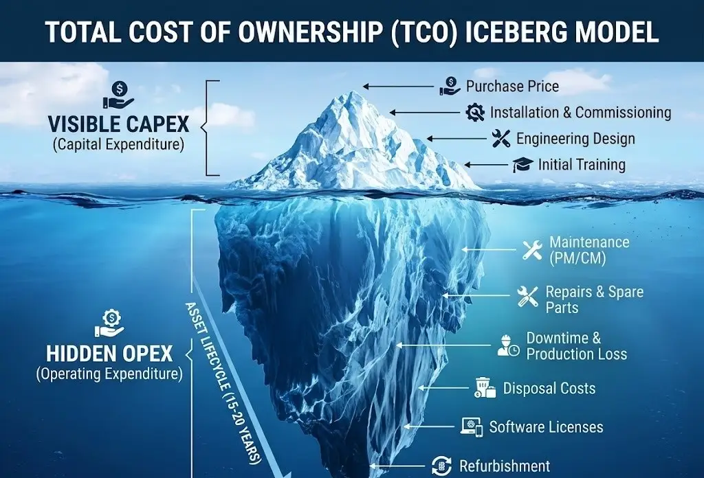
The highly visible tip of the iceberg—the capital expenditure (CapEx) required to purchase the automated valves, pneumatic actuators, electric actuators and centrifugal pumps—rarely accounts for the majority of the system’s true lifetime cost. The massive, hidden bulk submerged below the financial surface consists of continuous energy consumption, routine maintenance labor, the frequent replacement of degraded internal seals, and, most critically, the devastating financial impact of unplanned process downtime. In chemical processing or offshore environments, a single hour of halted production due to a seized valve stem can obliterate months of savings achieved through budget-oriented procurement.
An anonymized case study at a specialty high-corrosion chemical plant vividly illustrates this engineering-to-finance principle. The plant was experiencing frequent elastomer failures on standard 316L stainless steel butterfly valves handling a mild acidic slurry. By applying a rigorous, data-driven analysis matrix, the engineering team decided to upgrade the entire line to fully PFA-lined valves equipped with engineered ceramic trims. Initially, the procurement department resisted, noting that the CapEx for the new, highly specialized valves was visibly higher than their standard commercial replacements. However, this calculated engineering decision extended the maintenance replacement cycle from a mere six months to over three years of continuous, leak-free operation. By drastically reducing replacement labor, eliminating the cost of scrapped contaminated batches, and increasing overall plant uptime, this initial premium ultimately reduced the specific pipeline’s Total Cost of Ownership (TCO) by a highly significant margin, proving irrefutably that superior engineering pays for itself over the asset lifecycle.
The Vincer Valve Advantage: Eliminating OPEX at the Root
Optimizing TCO requires an expert partner who actively engineers operational risk out of your system before manufacturing begins. Founded in 2010, صمام فينسر is a national high-tech enterprise dedicated to providing comprehensive intelligent fluid control solutions. With over a decade of specialized industry experience, Vincer utilizes a rigorous 8-Dimensional Analysis Framework (evaluating medium, temperature, pressure, connection standard, control method, material, industry specifics, and installation space) to select the precise metallurgy and actuation logic for your specific requirements. This engineering-first approach directly mitigates the vast majority of hidden operational expenditures by ensuring the hardware is perfectly matched to the fluid dynamics from day one.
Furthermore, Vincer operates a 7,200-square-meter vertically integrated manufacturing facility equipped with an advanced CNC machining matrix. This autonomous production capability allows the delivery of fully certified (CE, SIL, FDA, ISO9001) electric and pneumatic fluid control solutions with remarkable efficiency. Standard fluid control products are typically delivered in just 7 to 10 working days, while complex customized solutions are engineered and shipped in 15 to 30 days. By streamlining production and offering a comprehensive product portfolio, Vincer consistently delivers highly competitive CapEx optimization while guaranteeing that your critical engineering projects stay strictly on schedule. Ultimately, partnering with Vincer empowers your facility to save project costs and “do more with less.”
Stop Compromising Between Quality and Budget
If you are engineering a critical fluid network and require valve solutions that refuse to compromise on safety while aggressively optimizing your project’s TCO, our engineering team is ready to analyze your parameters.