في كل مرة ترى فيها صمام فراشة في خط معالجة المياه، أو غرفة معدات التدفئة والتهوية وتكييف الهواء (HVAC)، أو برج تبريد، أو وحدة كيميائية متنقلة، فإنك تنظر إلى إحدى أبسط الآلات في مجال الأنابيب الصناعية: قرص مثبت على عمود يدور ربع دورة لفتح الصمام وإغلاقه. كيف يعمل الصمام الفراشي؟ يمكن شرح آليته في جملتين. أما فهم ما يمكنه وما لا يمكنه فعله فيستغرق بقية هذا المقال: سنستعرض الدوران بزاوية 90 درجة نفسه، ثم الأنواع المتفرعة منه، وقرار الأتمتة، وأخيرًا الظروف التي يتوقف فيها مبدأ العمل عن الانطباق.
ما هو الصمام الفراشي وكيف يعمل؟
الصمام الفراشي هو صمام ربع دورة يعمل على عزل التدفق أو تنظيمه عن طريق تدوير قرص حول عمود مركزي. ويُطلق مصطلح “الفراشة” على هذا القرص. وعندما يكون الصمام مفتوحًا بالكامل، يكون القرص موازيًا لاتجاه التدفق؛ أما عندما يكون مغلقًا بالكامل، فيكون قد استدار 90 درجة ليصبح عموديًا، مما يؤدي إلى سد فتحة الصمام (ويكيبيديا). ونظرًا لأن الشوط الكامل لا يتجاوز 90 درجة، فإن الصمام يفتح ويغلق بسرعة أكبر من الأنواع متعددة الدورات مثل الصمامات البوابية.
يستند هذا المبدأ بأكمله إلى أربعة أجزاء:
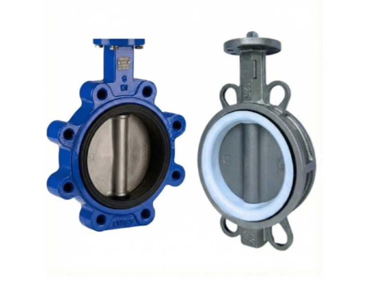
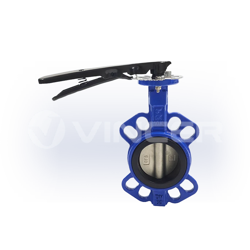
- النص — الغلاف الذي يتم تركيبه بين شفرات الأنابيب (من النوع الرقيق، أو ذي العروة، أو ذي الشفرتين).
- قرص — العضو الختامي؛ يدور لحجب التدفق أو السماح بمروره.
- الساق — ينقل حركة الدوران من المقبض أو المشغل إلى القرص.
- المقعد — سطح الإحكام الذي يضغط عليه القرص عند إغلاقه.
أقرب أنواع الصمامات إليه هو الصمام الكروي: فكلاهما من الأجهزة التي تعمل بربع دورة، وكلاهما يفتح ويغلق بحركة واحدة بزاوية 90 درجة. والفرق الذي يحدد كل قرار هندسي يتعلق به هو أن الكرة في الصمام الكروي تنسحب من مسار التدفق عند الفتح، بينما قرص الصمام الفراشي يظل في مجرى الأمور. هذه الحقيقة الهيكلية وحدها هي التي تجعل الصمام الفراشي غير كامل المجرى: فهو يسبب دائمًا بعض المقاومة عند فتحه، ولا يمكن تنظيف الأنابيب التي تحتوي عليه باستخدام أداة التنظيف (البيغ). وهذا هو الثمن الذي يُدفع مقابل خفة وزنه وصغر حجمه وتكلفته الأقل بكثير مقارنة بالصمامات الأخرى ذات الأقطار الكبيرة، وهي الحقيقة التي تحدد آليات الإحكام، وأنواع الفروع، وحدود الخنق في بقية هذا المقال.
أنواع الصمامات الفراشية: ثلاث طبقات هيكلية، مبدأ عمل واحد
هناك مبدأ عمل واحد فقط، والعديد من الأنواع. كل “نوع” من الصمامات الفراشية يعتمد على نفس الآلية التي تعمل بزاوية 90 درجة، مع تغيير طبقة هيكلية واحدة: كيفية تثبيت القرص على المقعد، وكيفية تركيب الصمام في الخط، وما هي المادة التي صُنع منها المقعد. اقرأ عن الطبقات الثلاث أدناه وستتمكن من تصنيف أي صمام فراشة متوفر في السوق في فئته المناسبة — أي التصميم هو الافتراضي، وأيها هو الأكثر استخدامًا، وأيها مخصص للحالات القصوى.
هيكل مانع التسرب: متحد المركز، ومزدوج الإزاحة، وثلاثي الإزاحة
الطبقة الهيكلية الأولى هي التلامس المانع للتسرب — أي كيفية تلامس القرص مع المقعد عند الإغلاق. ⭐ يُعد التصميم المتراكز (بدون إزاحة) النوع الأكثر شيوعًا من الصمامات الفراشية المتوفرة في السوق: يقع ساق الصمام على خط الوسط للقرص، وإغلاقه يشبه ضغط ختم على الورق: حيث ينزلق القرص على المقعد خلال الجزء الأخير من مسار الحركة. ويُعد هذا التلامس الانزلاقي مقبولاً تمامًا للمقاعد اللينة المستخدمة في تطبيقات المياه وأنظمة التدفئة والتهوية وتكييف الهواء، كما أنه يساهم في الحفاظ على انخفاض تكلفة الصمام. يُعد التصميم ذو الإزاحة المزدوجة الخيار القياسي للخطوط الأكبر حجمًا وعمليات التشغيل المتكررة — حيث يكون الجذع منحرفًا عن مركز القرص ومركز التجويف على حد سواء، بحيث يرتفع القرص عن المقعد فور فتحه بدلاً من أن ينزلق عليه. انخفاض الاحتكاك، وانخفاض التآكل: وهذا هو السبب في أن شبكات المياه البلدية تعمل بتصاميم مزدوجة الإزاحة. تصميم «الثلاثي الإزاحة» هو نموذج نادر من الفئة الراقية — ويتيح الإزاحة المخروطية الثالثة للقرص أن يلامس المقعد دون أي انزلاق على الإطلاق، وبالتالي يمكن أن يكون المقعد مصنوعًا من معدن صلب، ومُشكَّل آليًّا لضمان إغلاق محكم يمنع تسرب الفقاعات في ظل ظروف درجات الحرارة العالية والضغط العالي والاستخدامات المتعلقة بالهيدروكربونات.
| التصميم | كيف يتم تثبيت الختم | الاحتكاك والتآكل | المهام المعتادة | الموقع في السوق |
|---|---|---|---|---|
| متحدة المركز (إزاحة صفرية) | تضغط القرص مباشرةً على المقعد؛ ثم تنزلق عليه | أعلى معامل احتكاك بين الثلاثة | المياه، أنظمة التدفئة والتهوية وتكييف الهواء (HVAC)، المهام ذات الضغط المنخفض | ⭐ الأكثر شيوعًا — الإعداد الافتراضي للاستخدام اليومي |
| الإزاحة المزدوجة | تؤدي حركة الكامة إلى رفع القرص عن المقعد عند الفتح | انخفض الاحتكاك بشكل حاد | خطوط كبيرة، ضغط أعلى، دورات تشغيل متكررة — شبكات المياه | ⭐ المعيار الخاص بمهام الشبكة |
| الإزاحة الثلاثية | تلامس مخروطي بين المعدن والمعدن، بدون انزلاق | احتكاك ضئيل؛ يتركز التآكل في حالات الإغلاق | درجات الحرارة والضغط العالية، النفط، الغاز، المواد الكيميائية | نادر — يخضع للرسوم الجمركية الممتازة فقط |
هناك حد معين لا يكتب عنه أحد تقريبًا: إن جودة المقعد المعدني تتوقف كليًّا على آخر عملية إغلاق كاملة. فإذا تُرك صمام ثلاثي الإزاحة مفتوحًا جزئيًّا، أو انسدّ بفعل الحطام، أو لم يحصل على القوة الكافية بسبب مشغل أصغر من اللازم، فإن المقعد المعدني يتآكل، وهذا التآكل لا يمكن إصلاحه بالطريقة التي يمكن بها إصلاح تآكل المطاط الصناعي (تجربة ميدانية، منتدى هندسة الصمامات Eng-Tips).
وصلات الأطراف: رقاقة، وعروة، وذات حافتين
الطبقة الهيكلية الثانية تتعلق بكيفية تركيب الصمام في الخط، وهي تحدد أمرًا عمليًّا واحدًا: ما إذا كان بإمكانك أبدًا العمل على أحد جانبي الصمام دون تفريغ الخط بأكمله. ⭐ يُعد التوصيل بالرقاقة (من النوع الرقائقي) الشكل الأكثر استخدامًا: يقع الصمام محصوراً بين شفتين مثبتتين بمسامير طويلة تخترقهما — وهو تصميم مدمج ورخيص، لكن من المستحيل استخدامه في نهاية الخط. يُعد التوصيل بالنتوءات الخيار الذي يسهل صيانته: تتيح الملحقات الملولبة الموجودة على كلا الوجهين فصل كل جانب من جوانب الأنابيب بشكل مستقل، ولهذا السبب تُعتبر هذه الطريقة المعيار المتبع لعزل نهاية الخط. الوصلة ذات الحافتين هي الوصلة الفرعية المخصصة للأحمال الثقيلة: حواف خاصة بها، للأقطار الكبيرة والضغوط العالية.
ينطوي النوع ذو العروة على تحذير واحد: في حالة التشغيل في خط مسدود، يجب تزويده بفلنجة مغلقة، لأن معدل الضغط المسموح به ينخفض — فالصمام ذو العروة الذي يبلغ معدل الضغط المسموح به 150 psi عند تركيبه بين فلنجتين، ينخفض معدله إلى ما يقارب نصف ذلك عند تركيبه مع فلنجة واحدة (ويكيبيديا).
مادة المقاعد: المقاعد الناعمة مقابل المقاعد المعدنية
الطبقة الهيكلية الثالثة هي المادة التي تشكل الختم فعليًّا، وهي التي تحدد الحد الأقصى لدرجة الحرارة للمجموعة بأكملها. ⭐ تُستخدم المقاعد المريحة في الغالبية العظمى من تطبيقات الاستخدام العادي: يتشوه مادة مطاطية (EPDM، NBR، PTFE) بشكل طفيف حول حافة القرص عند إغلاق الصمام، مما ينتج عنه إحكام إغلاق محكم، وغالبًا ما يكون مانعًا لتسرب الفقاعات، في درجات الحرارة والضغوط العادية. المقاعد المعدنية هي مجال تخصصنا: يُغلق القرص على سطح معدني تم تصنيعه بدقة، ولا يُثبت هذا التصميم فعاليته إلا في الظروف التي تتسم بارتفاع درجات الحرارة أو الضغط أو التي تتسم بالتآكل، حيث تفشل المواد المرنة.
| المواد | أقصى درجة حرارة | الخدمة النموذجية |
|---|---|---|
| EPDM | 120 درجة مئوية (248 درجة فهرنهايت) | مياه الشرب — لا تؤثر على المذاق |
| NBR | 85 درجة مئوية (185 درجة فهرنهايت) | خدمات النفط والمياه |
| FKM | 180 درجة مئوية (356 درجة فهرنهايت) | مقاومة عامة للمواد الكيميائية والحرارة |
| PTFE / السيليكون | 200 درجة مئوية (392 درجة فهرنهايت) | وسائل الإعلام العدوانية، المهام المرتبطة بالبخار |
إذا تجاوزت هذه القيم، فإن المقعد يتلف — حيث يستمر مبدأ التشغيل في تدوير القرص، لكن الصمام يتوقف عن الإغلاق المحكم.
ضع هذه الطبقات الثلاث معًا وستتضح الصورة في السوق من تلقاء نفسها: الصمام اليومي الافتراضي هو من النوع الرقائقي ذو المقاعد اللينة والمتراكزة؛ أما الصمام الأساسي للشبكة فهو ذو المقاعد اللينة والمزدوج الإزاحة مع وصلة عروة، بحيث يمكن صيانته قسمًا تلو الآخر؛ وأما الصمام الفائق عالي الجودة فهو ذو المقاعد المعدنية والمزدوج الحواف والمثلي الإزاحة. إن اختيار صمام الفراشة يعني في الغالب تحديد المكان الذي يقع فيه دورك ضمن هذه الطبقات الثلاث.
يدوي أم آلي؟ نقطة اتخاذ القرار بشأن الصمام الفراشي
من الذي يقوم بتدوير العمود؟ هذا هو أول قرار حقيقي يواجهه المشتري، ولم يعد قرارًا محايدًا. يمكن تدوير آلية الـ 90 درجة نفسها يدويًّا (بواسطة رافعة أو علبة تروس)، أو بالهواء المضغوط (مشغل هوائي)، أو بواسطة محرك كهربائي (مشغل كهربائي) — وتعمل الصناعة بهدوء على جعل الأتمتة هي الخيار الافتراضي.
هناك ثلاث قوى ملحوظة تدفع هذا التحول. أولاً، بنية التحكم: أصبحت شبكات المصانع الآن تستخدم لغة PLC/SCADA و4–20 mA كلغة قياسية لها، لذا فإن الصمام الذي لا يمكن التحكم فيه من غرفة التحكم يحتاج إلى مشغل يدوي منفصل — وهو استثناء يجب تبريره، وليس الأمر الافتراضي. ثانيًا، العمالة: الصمام المزود بمشغل يزيل الحاجة إلى المشي، واستخدام مفتاح الربط، وإعادة الفحص من كل عملية تشغيل للصمام؛ فالمصانع تقلص عدد المشغلين، لا أتمتة الصمامات. ثالثًا، التطبيقات الجديدة: تعتبر أنظمة تبريد مراكز البيانات ومنشآت عصر الذكاء الاصطناعي الصمامات الفراشية المزودة بمشغلات أمرًا مفروغًا منه، ويظهر هذا الطلب في أرقام السوق — فقد بلغت قيمة سوق المشغلات العالمية (بجميع أنواعها: الكهربائية، والهيدروليكية، الهوائية) بلغت قيمته حوالي 71 مليار دولار أمريكي في عام 2025، ومن المتوقع أن تصل إلى حوالي 100 مليار دولار أمريكي بحلول عام 2030، أي ما يقارب 7% سنويًا (MarketsandMarkets، 2025).
إن البنية الهندسية الكامنة وراء كل هذا قد تم توحيدها بالفعل. تحدد المواصفة القياسية ISO 5211 واجهة التثبيت التي تتيح تثبيت مشغل من أي مصنع على صمام فراشة من أي مصنع آخر — وهذا بالضبط ما تبدو عليه الصناعة عندما تضع الأسس للأتمتة. لن يختفي صمام الفراشة اليدوي؛ لكنه في المشاريع الجديدة، يتحول من الخيار الافتراضي إلى الاستثناء. والسؤال الذي يطرح نفسه بعد ذلك هو: أي مشغل يجب اختياره — وهذا ما سنتناوله في القسم التالي.
مبدأ عمل الصمام الفراشي الهوائي: عند دخول الهواء، يدور القرص
الصمام الفراشي الهوائي هو صمام فراشي مزود بمشغل هوائي مثبت بمسامير — عادةً من خلال نفس شفة ISO 5211. يعمل الهواء المضغوط على تشغيل آلية الترس والمسنن داخل المشغل؛ ويقوم المشغل بتحويل ضغط الهواء إلى عزم دوران على ساق الصمام؛ وتقوم الساق بتدوير القرص بنفس الزاوية البالغة 90 درجة التي يقوم بها ذراع التشغيل اليدوي. ولا يتغير مبدأ عمل الصمام نفسه — بل تتغير فقط القوة المحركة.
المعلمات المهمة هي عزم الدوران وإمداد الهواء. كنطاق مرجعي للمهام التي تتطلب ربع دورة: توفر المشغلات ذات العمل المزدوج التي تعمل بنظام الترس والمسنن عادةً ما يقارب 8–4,700 نيوتن متر، وأنواع العودة الزنبركية حوالي 5–2,800 نيوتن متر، ووحدات سكوتش يوك الأكبر حجمًا ما يصل إلى حوالي 10,000 نيوتن متر، عند ضغوط إمداد تصل إلى 8 بار ودرجات حرارة محيطة تتراوح من حوالي −20 درجة مئوية إلى +80 درجة مئوية، مع استجابة شوط أقل من ثانية (بيانات سلسلة الشركة المصنعة). إذا لم يتمكن المشغل من توليد عزم دوران كافٍ لدفع القرص إلى الإغلاق الكامل في مواجهة ضغط الخط، فسوف “يتسرب” الصمام — أي يحدث تسرب حول القرص — بغض النظر عن جودة المقعد.
Single-Acting vs. Double-Acting: What Happens When the Air Goes Out
The first question engineers ask about pneumatic butterfly valves is what happens on air failure, and the answer is determined before the valve is ever ordered.
- Double-acting: air opens it, air closes it. If supply is lost, the valve stays where it is. Simple and cheap; no defined failure position.
- Single-acting (spring return): one direction is powered by air, the other by a spring. On air loss, the spring drives the valve to a defined fail-safe position — spring-to-close or spring-to-open.
Choosing between them is a process-safety decision, not a cost decision: chemical and water processes usually want spring-to-close (fail closed to contain the line), ventilation and dump services usually want spring-to-open. If your control system assumes “air loss = valve closes,” and the valve is double-acting, that assumption is fiction.
From On/Off to Modulation: Valve Positioners and Throttling
To make a pneumatic butterfly valve regulate rather than just open and close, it needs a valve positioner: a control loop that takes a 4–20 mA signal and moves the disc to a commanded angle, holding it there against process forces. This is where the butterfly’s flow characteristic enters the story, and it is not linear.
A butterfly valve has a roughly quick-opening characteristic: most of the flow change happens in the first part of the stroke. A small movement near the closed position produces a disproportionate flow swing, which is why a modulated butterfly valve is only comfortable working around the middle of its travel — engineering guidance puts the usable modulation band at roughly 30–60% open, with the valve often selected one nominal size smaller than the pipe so that the working point actually lands inside that band (Eng-Tips, valve engineering forum). What happens when you leave that band is covered later — but first, the other half of the automation story.
Specifying a pneumatic or electric butterfly valve?
Get the actuator matched to your duty — torque, fail-safe behavior and stroke time checked against your line size.
Ask for valve & actuator selectionMotorized Butterfly Valve Working Principle: Signal In, Torque Out
A motorized butterfly valve replaces the air muscle with an electric actuator: motor, gear train, and output drive mounted on the same ISO 5211 flange. The motor turns the gear train; the gear train multiplies torque and slows the output; the output turns the stem; the stem rotates the disc, to either of two positions (ON/OFF type) or to any commanded angle (modulating type with a 4–20 mA / 0–10 V signal).
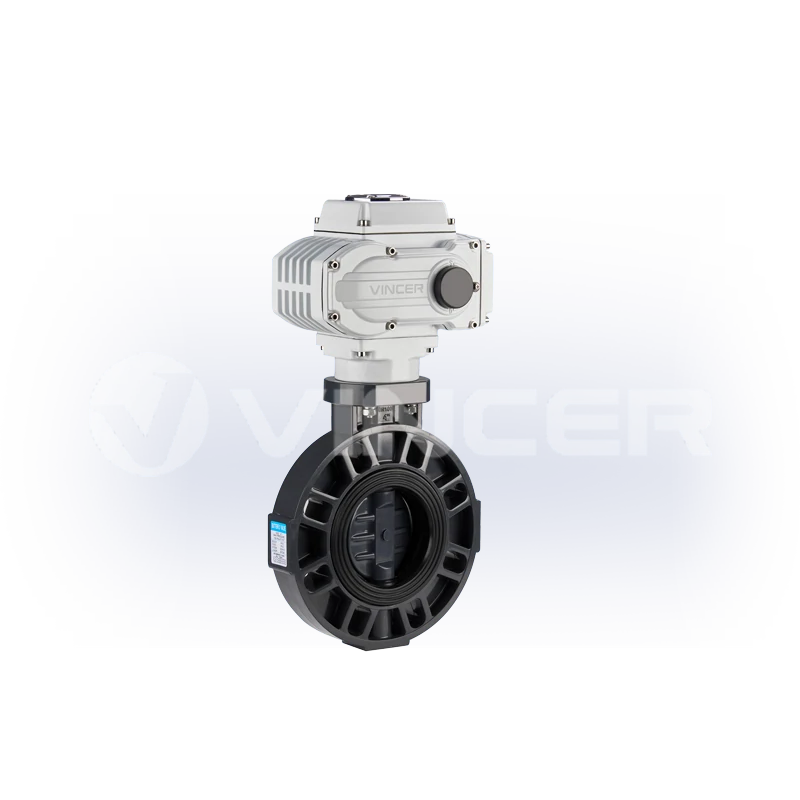
Torque and speed are the two numbers that decide whether the assembly does its job. As a reference band for quarter-turn electric actuators: output torques range from roughly 200 N·m for compact units (2.5–20 s stroke) up to about 4,000 N·m for large quarter-turn units (20–100 s stroke), with multi-turn versions beyond 10,000 N·m, in DC 12/24 V and AC 110/220/380 V variants (manufacturer series data). Electric actuation is the usual choice for precise modulating control, remote monitoring via PLC/SCADA, and sites without a reliable air supply.
How an Electric Actuator Turns the Disc — and Why Speed Matters
The power chain looks like this: signal → motor → gear reduction → output drive → stem → disc. The gear reduction is the part people misread. An electric actuator is slower than a pneumatic one because it trades speed for torque, and that slowness is often a feature, especially on large water lines.
Close a big butterfly valve too fast and you invite water hammer: the moving water column slams into the closing disc, and the pressure spike can damage valves, pipe supports, and pumps. A slow, controlled electric close over tens of seconds gives the water time to decelerate. When a pump station or water treatment spec calls for an electric butterfly valve, “how many seconds to close” is usually a deliberate engineering number, not an accident.
Electric vs. Pneumatic: Choosing the Driver for Your Duty
The two automation paths answer to different plant realities. The decision matrix that matters:
| البعد | كهربائي | هوائي |
|---|---|---|
| Speed | 20–100 s stroke — slow, controlled | Under 1 s — fast |
| Power source | Mains or DC supply | Compressed air — needs a dry, filtered supply |
| Hazardous areas | Explosion-proof electric actuators available (ATEX-rated) | No electrical spark in the actuator itself, but ATEX certification must still be verified per unit |
| Modulation | 4–20 mA precise positioning as standard | Needs a positioner for modulation |
| Failure behaviour | Stays put, or spring-return variant on power loss | Stays put (double-acting) or spring to a defined position (single-acting) |
| Maintenance | Motor and gear wear, occasional | Seal wear and air quality discipline |
Two cautions. First, “no spark” is not the same as “certified”: a pneumatic actuator’s inherent suitability for explosive atmospheres does not itself grant an ATEX rating. The complete assembly has to be certified. Second, ISO 5211 is the common language that lets an electric or pneumatic actuator from one manufacturer mount on a butterfly valve from another — so the actuator choice stays independent of the valve choice, and the working principle of each half can be matched to the duty separately.
That is also where buying the driver and the valve from the same factory pays off: the torque matching is done before the quote, not after installation. VINCER publishes its electric and pneumatic actuator range openly: quarter-turn electric units from 200 N·m (2.5–20 s stroke) up to 4,000 N·m (20–100 s), multi-turn versions to 10,000 N·m, plus explosion-proof and waterproof variants. Pneumatic rack-and-pinion AT/ATS/AW series run from 8–4,678 N·m double-acting and 5.7–2,792 N·m spring-return up to 10,000 N·m, with under-one-second stroke response and no electrical spark in the actuator itself. The same factory builds the valves those actuators bolt onto, including pneumatic actuated butterfly valves in wafer, flanged, sanitary, plastic, hard-seated and PTFE-lined versions, and electric butterfly valves from compact wafer and lugged types up to auto-reset power-off designs, in sizes from 2″ to 24″. One factory, one torque table, one set of pressure-test records, and the working principle of each half matched on paper before anything ships.
When the Working Principle Breaks: Throttling Limits and the 30–60% Rule
Everything above described the butterfly valve doing what it does well. This section is about where the principle stops holding, because that is the information that keeps plants out of trouble, and it is almost never written down in “working principle” articles.
The danger zone is below 30% open. At small opening angles, the flow area narrows to a crescent. Fluid velocity through it rises sharply, the disc sits at a steep angle, and local pressure can drop below vapour pressure. The result is cavitation: vapor bubbles forming and collapsing at the disc edge, eroding the seat and even the downstream pipe wall. Field experience puts the rule simply: a butterfly valve throttled below about 30% opening risks cavitation damage, and the damage typically shows up first on the seat (Eng-Tips).
The trap is sizing the valve the same size as the pipe. If you need to throttle, and the valve matches the line diameter, the required flow may only be achieved at 15–25% opening — exactly the cavitation-and-chatter zone. The standard fix in control practice: select the butterfly valve one nominal size smaller than the pipe for modulating duty, so the working point returns to a healthy mid-stroke position.
And the corollary for plant engineers: when the duty keeps a butterfly below 30% continuously, the answer is not a better butterfly — it is a different valve. The boundary matrix below is the horizontal version of everything above — scenario, valve, and the line not to cross:
| Scenario | Valve Choice | Boundary |
|---|---|---|
| On/off isolation, large water or gas lines | Concentric soft-seated butterfly | Perfect — do not throttle it |
| Frequent flow adjustment (raw or process water) | Butterfly one size smaller than pipe, kept in 30–60% band — otherwise a control valve | Continuous <30% opening = switch signal |
| High-temperature, high-pressure tight shut-off (oil, gas, chemical) | Triple-offset metal-seated butterfly | Full closure mandatory; partial closure wears the metal seat |
| End-of-line isolation with one side maintainable | Lug butterfly with blind flange | Pressure rating drops in dead-end duty |
| Slurries, solids-laden media | Knife gate valve | Butterfly seats wear quickly on abrasives |
These boundaries are why the standards exist: butterfly valves for industrial duty are designed and tested to norms such as EN 593 (industrial butterfly valves) and API 609 (butterfly valve standard), and matching valve, seat, and actuator to the duty is precisely what a proper selection process, not a price sheet, is for.
What the Working Principle Means for the People Buying Valves
That last boundary, “when the duty keeps a butterfly below 30%, the answer is a different valve,” is a decision someone has to own. In the projects where these valves are specified, that ownership is exactly where the money leaks, because the people who choose the valve are usually not the people who suffer the failure.
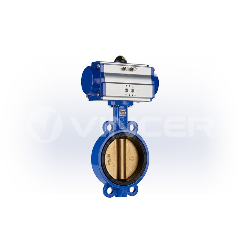
Look at what actually happens in the field. Plant teams throttling raw or process water with a butterfly valve watch the seat die within a short operating window and the valve lose both control and isolation duty, the classic “seat damage in flow-adjustment service” story from the engineering forums. The root causes are always the same three, and all three are decisions made before the valve is ever bolted in. The valve was sized to match the pipe instead of the duty. The working opening was left in the 15–30% zone instead of the 30–60% band. And the seat material was chosen by price rather than by media temperature. None of these show up on a drawing. They show up as downtime, and downtime is the most expensive line item on any valve’s lifetime bill.
For the people buying these valves, the translation is direct. In project procurement, put three clauses in the specification: the valve-to-pipe size ratio for any modulating service, the required working opening band, and the seat material temperature ceiling for the actual media — and the seat-damage failures largely stop being your problem. For equipment OEMs, document the failure behaviour (fail-open or fail-closed on air/power loss) in the selection documents, because a control philosophy that assumes the wrong failure position is a safety incident waiting for a power cut. And when comparing suppliers, price the selection as much as the valve: an assembly that cannot close fully because the actuator is under-torqued is a leak, a rework, and a claim — not a discount.
Three clauses that belong in the specification
Now for where the money actually sits in this product family — because it matters for every buyer, and especially for distributors and equipment builders deciding what to stock. A bare butterfly valve is close to a commodity: its price is on every directory, and its margin gets squeezed toward zero. The actuated assembly is a different product. The moment you add an actuator, the value moves into things a catalogue price cannot express: torque matching against the valve’s actual seat load, the ISO 5211 interface decision, the fail-safe logic, the control integration. That is engineering work, and engineering work cannot be commoditized. The market data in the decision-point section said the same thing from the demand side — automation is where the growth is — and the profit follows the same direction. If you are building a product line or a stock list around butterfly valves, the defensible position is the actuated assembly: valve plus actuator, matched and tested as one unit. The bare valve is the entry ticket; the actuator is where the margin lives.
That is also why the supplier question is really a capability question. The working principle itself is public knowledge — every manufacturer’s website explains the 90° turn. What separates suppliers is what happens before the quote: whether the valve, seat, and actuator are matched to media, temperature, pressure, connection standard, control method, material, and industry characteristics — the full selection screen, not just the price column. On the delivery side, the published figures matter. Stock items leave in about five working days, custom builds in about twenty, per the manufacturer’s own published lead times (pneumatic valve page FAQ). And when a valve “won’t close,” “won’t install,” or “leaks,” the after-sale response — free spare parts, remote technical guidance, engineers who analyse before replacing — is the difference between a week of downtime and a morning.
When the working principle has to be matched to a real duty — media, temperature, pressure, connection standard, control method, body material and industry characteristics — that matching is selection engineering, and it is where the supplier’s actual capability shows. Send your duty to VINCER’s selection engineers and get a proposal within 48 hours, starting from their butterfly valve range.
Get your butterfly valve selection checked against the 30–60% rule
Send your line size, media, temperature and pressure — the engineering team replies with a selection proposal.
Request a selection proposalReferences
- Wikipedia. “Butterfly valve” — quarter-turn definition, disc-in-flow, wafer/lug dead-end pressure derating. https://en.wikipedia.org/wiki/Butterfly_valve
- Tameson. “What is a Butterfly Valve?” — seat material temperature limits, ISO 5211/NAMUR mounting, selection criteria. https://tameson.com/pages/butterfly-valve
- Eng-Tips (Valve Engineering forum). “Butterfly Valves used for flow adjustment in raw water service experiencing valve seat damage” — 30% cavitation line, 30–60% throttling band, oversized-valve rule. https://www.eng-tips.com/threads/butterfly-valves-used-for-flow-adjustment-in-raw-water-service-experiencing-valve-seat-damage.459593/
- MarketsandMarkets. “Actuators Market — Global Forecast to 2030” — USD 71.22B (2025) → USD 100.41B (2030), CAGR 7.1%, all actuator types (electric/hydraulic/pneumatic). https://www.marketsandmarkets.com/Market-Reports/global-actuators-market-59465451.html
- VINCER Valve. Butterfly valve series — wafer/lug/double-flanged, 2″–24″, sealing options. https://www.vincervalve.com/vincer-butterfly-valve-series/
- VINCER Valve. Contact for a quote. https://www.vincervalve.com/contact-for-a-quote/
- VINCER Valve. Homepage. https://www.vincervalve.com/
- VINCER Valve. Electric and pneumatic actuator range — VQ/VM quarter-turn, multi-turn, explosion-proof, waterproof electric; AT/ATS/AW pneumatic; torque 200 N·m–10,000 N·m. https://www.vincervalve.com/vincer-automatic-valve-actutors/
- VINCER Valve. Pneumatic actuated valves — pneumatic butterfly valve family (wafer, flanged, sanitary, plastic, hard-seated, PTFE-lined); response <1 s; hazardous-environment suitability. https://www.vincervalve.com/pneumatic-actuated-valve/