نظرة عامة على تصنيع خلايا البطاريات
يعمل تصنيع خلايا البطاريات على تحويل المواد الخام — مثل مركبات الليثيوم، والجرافيت، والرقائق المعدنية، والمذيبات، والإلكتروليت — إلى وحدات تخزين للطاقة الكهروكيميائية التي تزود الطاقة لكل شيء بدءًا من الهواتف الذكية مرورًا بالمركبات الكهربائية وصولاً إلى أنظمة التخزين على نطاق الشبكة. وفي جوهره، يُعد هذا التحدي هندسيًّا كيميائيًّا دقيقًا يُنفَّذ على نطاق هائل: فمصنع «جيجا» حديث واحد ينتج سعة تزيد عن 30 جيجاوات/ساعة سنويًّا، مما يعني أن ملايين الخلايا الفردية تخرج من خط الإنتاج كل يوم.
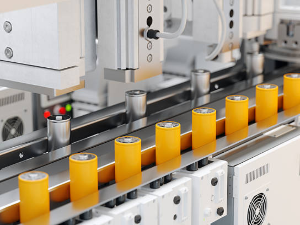
تتألف عملية التصنيع من ثلاث مراحل رئيسية. تصنيع الأقطاب الكهربائية تحول مساحيق المواد النشطة إلى رقائق معدنية مطلية بدقة، وهي رقائق الأنود والكاثود التي تقوم بتخزين وإطلاق أيونات الليثيوم. تجميع الخلايا تقوم بتركيب هذه الأقطاب الكهربائية مع الفواصل داخل غرف نظيفة فائقة الجفاف، ثم تقوم بحقن الإلكتروليت الذي يتيح نقل الأيونات. تشطيب الخلايا تُخضع المرحلة الأطول والأغلى كل خلية لدورات الشحن والتفريغ الأولى، مما يؤدي إلى تكوين طبقة «المرحلة البينية للكهرباء الصلبة» (SEI) الحاسمة التي تحدد العمر التشغيلي للخلية.
يأخذ المنتج النهائي أحد الأشكال المادية الثلاثة. الخلايا الأسطوانية تستخدم الأشكال المألوفة 18650 و21700 و4680 بنية ملفوفة على شكل “لفافة الهلام” داخل غلاف معدني صلب. وتُفضل هذه الأشكال لما تتمتع به من متانة ميكانيكية وإمكانية تصنيع سريعة. الخلايا المنشورية يُخزن هذا الصندوق مجموعات الأقطاب الكهربائية، سواء كانت ملفوفة أو مكدسة، داخل علبة صلبة مستطيلة الشكل، مما يضمن أقصى قدر من كفاءة التعبئة في حزم بطاريات المركبات. الخلايا الجرابية استخدم غشاءً مرنًا مغلفًا بالألمنيوم. فهي توفر أعلى كثافة طاقة بالوزن، لكنها تتطلب أقصى درجات الحذر في التعامل معها أثناء التجميع.
ما يجعل كل هذا صعبًا للغاية هو الدقة المطلوبة. يجب أن تظل طبقات طلاء الأقطاب الكهربائية ضمن نطاق ±2 ميكرون من السماكة المستهدفة عبر لفائف رقائق معدنية يبلغ طولها كيلومترًا واحدًا وتتحرك بسرعة 80 مترًا في الدقيقة. يجب أن تتوافق طبقات الأقطاب الكهربائية في نطاق 200 ميكرون أثناء التكديس، وهو ما يعادل ضعف عرض شعرة الإنسان تقريبًا. وتتطلب بيئة التجميع درجات حرارة نقطة الندى تتراوح بين -40 درجة مئوية و-60 درجة مئوية، وهي أكثر جفافًا من أي صحراء طبيعية على وجه الأرض. ويجب أن تجتاز كل خلية على حدة الاختبارات الكهربائية في نهاية خط الإنتاج. فخلية واحدة معيبة كفيلة بإتلاف حزمة بطاريات بأكملها.
وتستند كل خطوة من هذه الخطوات إلى بنية تحتية واسعة النطاق للتحكم في السوائل — تتألف من المضخات والأنابيب والصمامات — التي تعمل على نقل وقياس وعزل الملاط والمذيبات والإلكتروليتات والسوائل الحرارية في جميع أنحاء المصنع. إن فهم أين ولماذا تكتسب الصمامات أهمية في إنتاج البطاريات ليس مجرد مسألة ثانوية؛ بل هو أمر أساسي لتصميم وتشغيل خط إنتاج موثوق به.
تصنيع الأقطاب الكهربائية: أساس أداء الخلايا
يُعد تصنيع الأقطاب الكهربائية العامل الحاسم في نجاح أو فشل أداء البطارية. فكل خطوة من الخطوات الأربع المتتالية — وهي الخلط، والطلاء والتجفيف، والتمليس، والتقطيع — تنطوي على معيار جودة واحد لا يمكن التنازل عنه. ولا يمكن تصحيح أي عيب يحدث في أي من هذه الخطوات في المراحل اللاحقة. فإذا تم تصنيع القطب الكهربائي بشكل صحيح، تكون قد أرست أساسًا متينًا؛ أما إذا أخطأت في ذلك، فلن يتمكن حتى التجميع والتشكيل الخاليان من العيوب من إنقاذ الخلية.
الخلط: تحويل المساحيق إلى ملاط متجانس
تبدأ البطارية بأكملها كخليط من المساحيق: المادة الفعالة (أكسيد معدن الليثيوم للكاثود، والجرافيت للأنود)، ومضافات الكربون الموصلة، والمواد الرابطة البوليمرية، وهي معلقة في مذيب — غالبًا ما يكون N-ميثيل-2-بيروليدون (NMP) — في عملية تصنيع الكاثود. وتحدد جودة الملاط بشكل مباشر مدى اتساق كل خطوة تصنيع لاحقة.
هناك طريقتان للخلط. الخلط على دفعات تستخدم الخلاطات الكوكبية، وهي أوعية كبيرة مزودة بشفرات تدور في مسار دائري تعمل على قص المكونات وتشتيتها على مدار فترة تتراوح بين ساعتين و8 ساعات لكل دفعة. وهي تقنية مألوفة ومرنة، ولا تزال هي السائدة في خطوط الإنتاج التجريبية وعمليات الإنتاج على نطاق أصغر. الخلط المستمر تقوم آلات البثق ثنائية اللولب بتغذية المواد الخام من أحد طرفيها وإخراج الملاط النهائي من الطرف الآخر، مما يحقق تجانسًا أفضل في غضون دقائق بدلاً من ساعات. ويقابل ذلك ارتفاع التكلفة الرأسمالية الأولية وانخفاض المرونة في إجراء تغييرات متكررة في التركيب الكيميائي.
يُعد اللزوجة المعلمة الرئيسية لمراقبة الجودة، حيث يتم الحفاظ عليها عادةً في نطاق يتراوح بين 3,000 و10,000 سنتيبواز (cP). فإذا كانت اللزوجة منخفضة جدًّا، فإن الملاط يترسب ويتقسم إلى طبقات داخل قادوس الطلاء، مما يتسبب في حدوث تدرجات في الكثافة عبر القطب الكهربائي. أما إذا كانت اللزوجة مرتفعة جدًّا، فلن يتمكن رأس الطلاء من ترسيب طبقة موحدة. كما أن توزيع حجم الجسيمات مهم بنفس القدر: يجب أن تكون جسيمات المادة الفعالة التي يتراوح حجمها بين 10 و20 ميكرون موزعة بشكل متجانس، دون وجود تكتلات كبيرة بما يكفي لتمزيق فجوة الطلاء أو تكوين نقاط محلية عالية المقاومة.
من منظور معالجة السوائل، تتطلب محطة الخلط صمامات قادرة على الجرعات الدقيقة للمكونات. تمنع الصمامات الكروية ذات التصميمات ذات الممر الكامل والمجوفة تراكم الملاط في المناطق الميتة حيث يمكن أن تجف المواد وتلوث الدفعة التالية. أما الصمامات الفراشية ذات التصميم الذي يقلل من المساحات الميتة إلى أدنى حد، فتتعامل مع التدفقات الكاشطة والمليئة بالجسيمات على جانب التفريغ. ونظرًا لأن مادة NMP هي مركب عضوي متطاير ومذيب قابل للاشتعال في آن واحد، يجب أن تحمل أي صمام أو مشغل في منطقة الخلط شهادة ATEX لضمان التشغيل المقاوم للانفجار.
الطلاء والتجفيف الترسيب الدقيق بسرعة
تتم عملية الطلاء عند نقطة التقاء الملاط بالرقائق المعدنية. يتم ترسيب طبقة رقيقة من الملاط الكهربائي على رقاقة معدنية لجمع التيار: النحاس (بسمك 8 إلى 12 ميكرومتر عادةً) للأنود، والألومنيوم (12 إلى 20 ميكرومتر) للكاثود. والمعيار المتبع في الصناعة هو الطلاء باستخدام قالب الشق، الذي يدفع الملاط عبر فجوة مصنعة بدقة إلى شريط الرقاقة المتحرك، مما يحقق توحيدًا في سماكة الطبقة الرطبة في نطاق ±1.5 إلى 2.0 في المائة عبر العرض الكامل.
ثم تدخل الرقاقة المطلية إلى فرن تجفيف متعدد المناطق. ويمكن أن يصل طول هذه الأفران إلى 80 مترًا، مع سرعات ناقل تصل إلى 80 مترًا في الدقيقة، وتتراوح درجات حرارة المناطق من 80 درجة مئوية عند المدخل — لتجنب تكوّن طبقة قشرية على السطح الرطب — إلى 160 درجة مئوية في المناطق اللاحقة حيث تتم معظم عملية إزالة المذيب. يؤدي التسخين بالحمل الحراري والأشعة تحت الحمراء إلى طرد مادة NMP. ويمر الهواء العادم المشبع بالمذيبات عبر نظام استرداد — عادةً ما يكون وحدة تكثيف أو امتصاص — يلتقط أكثر من 90% من المذيب لإعادة استخدامه. ويخدم ذلك كلاً من الامتثال للمعايير البيئية وتقليل تكاليف التشغيل: فاسترداد المذيبات وحده يمكن أن يمثل حوالي 15% من إجمالي استهلاك الطاقة في تصنيع الأقطاب الكهربائية.
تتسم متطلبات التحكم في السوائل في هذه المرحلة بأنها كبيرة. يجب أن توفر مضخة التغذية الخاصة برأس الطلاء تدفقًا خاليًا من النبضات. فأي تقلب في الضغط يؤثر بشكل مباشر على تباين سماكة الطلاء. وتتطلب معالجة الهواء في منطقة التجفيف استخدام مجموعات من المخمدات ذات التحكم المتغير للحفاظ على أنماط درجة حرارة دقيقة على طول كل متر من الفرن. وفي حلقة استرداد المذيبات، يجب أن تقاوم الصمامات التي تتلامس مع بخار NMP الساخن كل من التأثيرات الكيميائية والدورات الحرارية. ويُعد الفولاذ المقاوم للصدأ 316L الحد الأدنى المطلوب. وتُستخدم المكونات المبطنة بـ PTFE في الأماكن التي يتجمع فيها سائل NMP المكثف داخل أجسام الصمامات بين دورات الإنتاج.
التكوير الضغط لزيادة الكثافة والالتصاق
بعد التجفيف، يصبح طلاء القطب الكهربائي طبقة مسامية ذات التصاق ضعيف، تبلغ نسبة الفراغات فيها ما بين 40 إلى 60 في المائة تقريبًا. وتتمثل عملية الكالندرة في تمرير هذه الرقاقة المطلية بين أسطوانتين فولاذيتين مُسخنتين تحت ضغط عالٍ، مما يؤدي إلى ضغط الطلاء حتى الوصول إلى درجة المسامية المستهدفة (التي تتراوح عادةً بين 20 إلى 40 في المائة) وربطه بإحكام بمجمع التيار.
تختلف معلمات عملية الكلندرة باختلاف التركيب الكيميائي. فقد يتم كلندرة كاثود NMC عالي الطاقة ليصل إلى كثافة تتراوح بين 3.4 و3.7 غ/سم³. أما كاثود LFP، الذي يتميز بكثافة مادية أقل بطبيعته، فيستهدف كثافة تتراوح بين 2.2 و2.5 غ/سم³. وتتراوح درجات حرارة الأسطوانات بين 80 درجة مئوية و150 درجة مئوية. تتراوح قوى الضغط الخطية عادةً بين 10 و20 كيلونيوتن لكل سنتيمتر من عرض الأسطوانة. ويتم التحكم في فجوة الأسطوانة بدقة تصل إلى الميكرون. فإذا كانت الفجوة واسعة جدًّا، فإن المسامية الزائدة تحد من كثافة الطاقة. أما إذا كانت ضيقة جدًّا، فإن المسام تنهار تمامًا بحيث لا يستطيع الإلكتروليت ترطيب القطب الكهربائي أثناء التعبئة، مما يؤدي إلى إضعاف قدرة معدل الشحن وعمر الدورة. ويجب أن يظل ارتداد السماكة بعد الكالندرة — وهو تأثير استرخاء لزوجي مرن — أقل من 5 في المائة. وإلا فلن يتناسب القطب بشكل صحيح مع غلاف الخلية.
تتطلب الأنظمة الهيدروليكية أو الكهروميكانيكية التي تتولى ضبط موضع أسطوانات المكبس تحكمًا مستقرًا وسريع الاستجابة في الضغط. ويجب أن تحافظ المنظمات النسبية الهوائية الموجودة في نظام تشغيل فجوة الأسطوانات على نقطة الضبط ضمن أجزاء من المليمتر تحت الحمل المستمر. وصمام التحكم في الضغط الذي يتعطل أو ينحرف عن الضبط لا يؤدي إلى توقف خط الإنتاج، ولكنه ينتج عدة مئات من الأمتار من الأقطاب الكهربائية غير المطابقة للمواصفات قبل أن يلاحظ أحد ذلك.
Slitting & Vacuum Drying Final Electrode Prep
The last two steps prepare the electrode for cell assembly. التقطيع cuts the wide “mother roll” into narrower “daughter rolls” matching the final electrode dimensions. Traditional mechanical slitting uses rotary knives fast and proven, but blade wear gradually increases burr height. Laser slitting eliminates tool wear entirely and produces cleaner edges with burrs under 10 microns, but requires careful management of the heat-affected zone to avoid degrading the active material near the cut edge. Burr control is not cosmetic: a metal burr tall enough to pierce the separator creates an internal short circuit. In a pack containing thousands of cells, that single defect can trigger thermal runaway.
Vacuum drying is the insurance policy. Coated electrodes absorb trace moisture from ambient air. Even a few hundred parts per million of residual water inside a finished cell will react with the lithium hexafluorophosphate (LiPF₆) electrolyte salt to generate hydrofluoric acid (HF) which etches the cathode, consumes active lithium, and generates gas. Electrodes are baked under vacuum at 80 to 120°C for 6 to 24 hours, bringing residual moisture below 500 ppm or below 200 ppm for moisture-sensitive chemistries like NMC811. The vacuum chamber isolation valves must seal reliably over thousands of cycles. A single leak during the 18-hour bake cycle reintroduces moisture and wastes an entire batch.
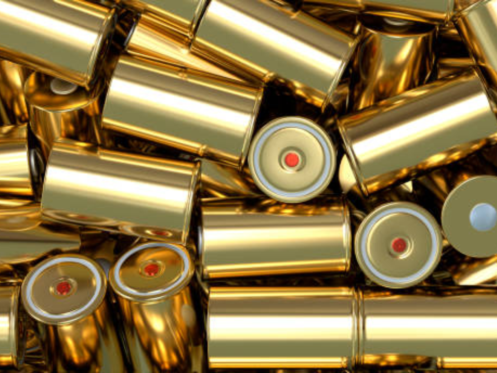
Cell Assembly Where Precision Meets Cleanliness
Once the electrodes are ready, the manufacturing environment transforms. Cell assembly takes place inside dry rooms where the dew point is held between -40°C and -60°C equivalent to roughly 0.08 percent relative humidity at room temperature. Workers wear full protective suits not to protect themselves from the product, but to protect the product from themselves. A single fingerprint contains enough moisture and salts to contaminate a cell. The air is filtered to ISO Class 7 or 8 cleanliness. Separate production lines for anodes and cathodes prevent cross-contamination between the two electrode chemistries.
Notching & Separation Cutting Electrodes to Shape
Before stacking or winding, the slit electrode rolls must be cut into individual sheets of precise dimensions. The uncoated foil area along one edge becomes the current-collector tab. Mechanical die punching is fast and well-established but suffers from progressive tool wear burr height increases with every thousand strokes, requiring regular maintenance intervals. Laser notching uses a pulsed beam to vaporize the cut path, producing consistent edge quality regardless of cycle count and enabling rapid shape changes through software rather than tooling swaps. The trade-off centers on capital cost and throughput: a mechanical die line runs faster at lower equipment cost, but a laser system eliminates the hidden cost of burr-related defects downstream.
Stacking vs. Winding The Core Assembly Decision
This is the fork in the road where cell format is determined. اللف takes continuous strips of anode, separator, cathode, and a second separator layer, and winds them around a mandrel into a cylindrical or flattened “jelly-roll.” It is the dominant process for cylindrical cells, hitting up to 30 cells per minute from a single winding station. The critical process variable is winding tension. Too loose creates gaps that increase internal resistance. Too tight compresses the separator and reduces its porosity. Uneven tension across the web width causes telescoping defects where layers shift axially. Wound cells naturally have fewer current-collector tabs typically one or two which limits peak power capability but simplifies manufacturing.
التكديس alternately layers individual sheets of anode, separator, and cathode, like building a deck of cards one by one. The Z-folding method uses a single continuous separator strip folded in a zigzag pattern, achieving placement precision within 200 microns. Single-sheet stacking uses robotic vacuum grippers to pick and place individual electrode sheets at rates approaching 0.15 seconds per piece on advanced multi-station equipment. Stacked electrodes produce cells with lower internal resistance and better rate capability because every layer connects directly to a current-collector tab. The trade-off: the equipment is more complex and costs more up front.
| البعد | Winding (Jelly-Roll) | Stacking (Z-Fold or Single-Sheet) |
|---|---|---|
| Typical cell format | Cylindrical, some prismatic | Pouch, prismatic |
| Throughput | High (up to 30 ppm) | Moderate (0.15 s/pcs per station) |
| دقة المحاذاة | ±300 500 μm | ±200 μm |
| المقاومة الداخلية | Higher (fewer tabs, longer current path) | Lower (every layer has a tab) |
| Equipment complexity | أدنى | أعلى |
| Capital cost | أدنى | أعلى |
| الأفضل لـ | High-volume cylindrical cells | High-power, long-cycle-life cells |
Electrolyte Filling The Precision Dispensing Challenge
Electrolyte filling depends on precision fluid control more than any other assembly step. A typical 5 Ah pouch cell receives 4 to 5 grams of electrolyte LiPF₆ lithium salt dissolved in a blend of organic carbonate solvents with proprietary additive packages. Filling must happen under vacuum to draw electrolyte into every pore of the electrode stack. Fill weight must be accurate to within ±1 to 2 percent. Underfill by even half a gram starves a portion of the electrode of ionic conductivity, creating dead zones that permanently reduce capacity. Overfill wastes expensive electrolyte and risks swelling during formation.
The valve delivering this dose operates under uniquely challenging conditions. LiPF₆ hydrolyzes on contact with moisture to form HF acid. Every wetted surface must be chemically inert stainless steel components need PTFE or PFA lining, and polymer seals must resist both the organic solvents and the trace acid. The dispensing valve must open and close with sub-millisecond repeatability to control shot size. It must seal drip-tight between cycles. Even a single droplet of electrolyte on the cell’s sealing surface prevents a hermetic closure.
Two valve technologies dominate this application. Diaphragm valves use a flexible PTFE or EPDM membrane to isolate the actuator from the fluid path, eliminating dynamic seal leakage. Their wetted surfaces the valve body interior and diaphragm face are easily lined with PTFE or PFA for full chemical compatibility. The trade-off is cycle speed: diaphragm valves run slower than poppet or jet valves, capping throughput on high-speed lines. Piezo-actuated jet valves hit the highest dispensing speeds up to 1,000 Hz on advanced systems by using a piezoelectric stack to rapidly deform a diaphragm, ejecting micro-droplets as small as 0.5 nanoliters. They dominate high-throughput stations but demand meticulous maintenance. Particulate contamination clogs the micro-orifice. Piezo performance degrades above the Curie point.
For both technologies, drip-free shutoff is non-negotiable. A droplet of electrolyte left on the fill nozzle lands on the cell’s heat-seal area, preventing a hermetic seal. The resulting latent failure may not show up until the cell has been in the field for months. The valve’s internal geometry must retract the fluid column slightly at the end of each dispense cycle a feature achieved through careful balancing of supply pressure, orifice diameter, and diaphragm stroke.
Cell Finishing Formation, Aging & Quality Verification
Cell finishing is where the cell becomes electrochemically alive and where manufacturing time and cost concentrate. Formation and aging together occupy one to three weeks of process time and consume roughly one-third of total cell manufacturing cost. The reason is simple: enormous capital tied up in formation cycling equipment, plus the factory floor space needed to hold cells during aging.
| Stage | Purpose | Key Parameters | Typical Duration | Common Defects Detected |
|---|---|---|---|---|
| التدريب | Build the SEI passivation layer on the anode | 0.1C 0.5C charge rate; voltage ceiling 3.0V (LFP) or 4.2V (NMC) | 12 24 hours | Uneven SEI, lithium plating, gas generation |
| Aging | Stabilize electrochemistry; screen for internal micro-shorts | 30 50°C elevated-temperature storage | Days to 3 weeks | Voltage drop >0.05 V/day (self-discharge) |
| End-of-Line Testing | Verify capacity, internal resistance, leakage, and appearance | 100% testing: capacity at 1C, EIS at 1 kHz, leak test | Minutes per cell | Low capacity, high IR, seal failure |
التدريب is the cell’s first controlled charge. At low current typically 0.1C to 0.5C lithium ions intercalate into the anode graphite and simultaneously react with electrolyte solvent molecules at the electrode surface. This forms the solid-electrolyte interphase, a nanoscale passivation film. The SEI layer is electrically insulating, which prevents further electrolyte decomposition, but ionically conductive, which lets lithium ions pass through. Its quality determines the cell’s calendar life, cycle life, and safety margin. Formation consumes 5 to 10 percent of the cell’s active lithium inventory lithium permanently bound in the SEI that cannot participate in future charge-discharge cycles.
During formation, gases primarily CO₂ and ethylene evolve from electrolyte decomposition and must be removed. For pouch cells, this means piercing the gas pocket in a vacuum chamber and resealing the final edge. For cylindrical and prismatic cells, formation typically occurs before final sealing, with degassing integrated into the process flow.
Aging follows formation. Its job is quality screening. Cells sit at elevated temperatures (30 50°C) for days to weeks while their open-circuit voltage is monitored. A cell with an internal micro-short caused by a metal particle contaminant or a separator pinhole shows a steadily dropping voltage as the short slowly discharges it. The screening threshold: voltage drop exceeding 0.05 volts per day. Cells that pass aging proceed to end-of-line testing. Cells that fail are scrapped or, for high-value large-format cells, sent for failure analysis.
The thermal management behind this entire stage depends on reliable fluid control. Formation cycling cabinets generate substantial heat. Chilled water loops supplied at 7°C, returning at 12°C must remove it. Aging chambers require precise temperature uniformity across every shelf so every cell ages under identical conditions. Both systems depend on modulating control valves that hold a temperature setpoint within ±1°C. A stuck-open cooling valve can drop chamber temperature by 5°C within an hour, invalidating aging data for thousands of cells.
The Hidden Backbone Fluid Control Infrastructure in Battery Production
If the electrodes are the muscle and the electrolyte is the blood of a battery factory, the valve network is the circulatory system the arteries and capillaries that move, meter, and isolate every process fluid across every production zone. A wrong valve selection wrong material, dead-leg geometry, or inadequate sealing rarely stops a production line outright. Instead, it erodes yield slowly and silently. The damage shows up months later as a higher warranty-return rate, with a root cause nearly impossible to trace back to a $200 component installed two years earlier. This section maps the four critical fluid control domains in battery cell manufacturing and the valve technologies that serve each.
Slurry & Solvent Handling The Abrasive & Corrosive Frontline
The mixing and coating areas handle the most mechanically and chemically aggressive fluids in the entire factory. Electrode slurry is a dense, abrasive suspension ceramic-adjacent metal oxide particles in a solvent carrier that scores standard stainless steel valve seats within months. NMP, the dominant cathode solvent, aggressively swells common elastomer seals. A Buna-N O-ring can degrade to the point of leakage within weeks of continuous exposure.
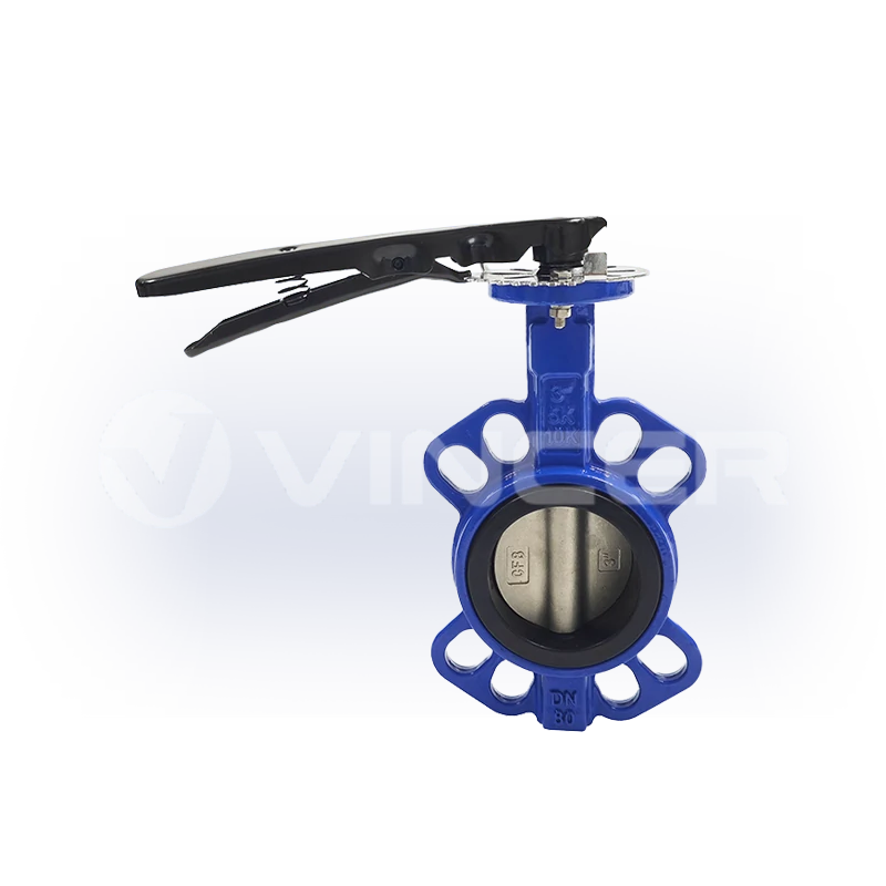
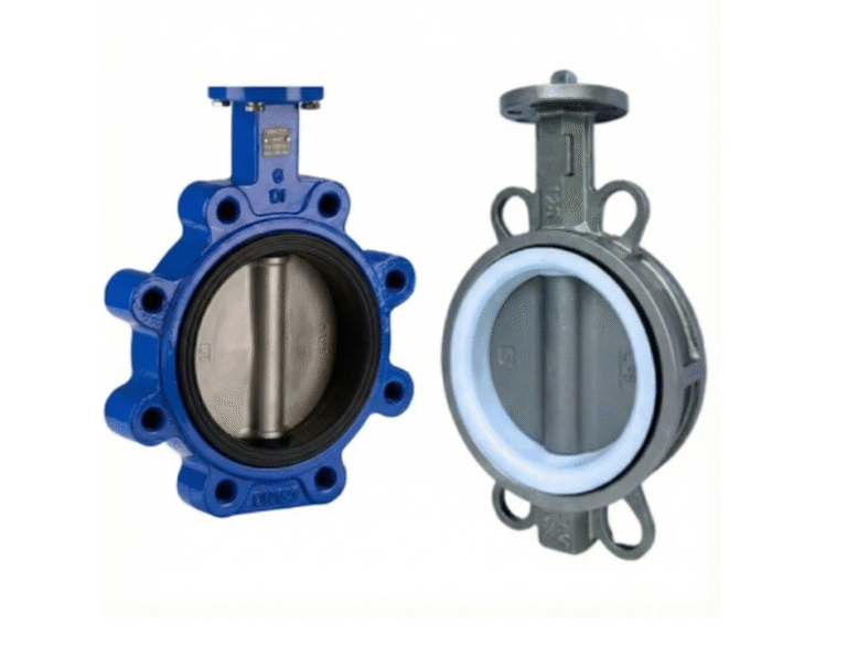
Valve selection in this zone follows three rules. First, full-bore ball valves with cavity-filled seats are the default for slurry lines. The spherical ball presents no obstruction to flow when open. This eliminates dead zones where slurry stagnates, dries, and forms hard deposits that break loose and contaminate downstream batches. Second, butterfly valves with PTFE or reinforced EPDM seats offer a lighter, more economical option for larger-diameter lines solvent storage tank outlets, ventilation ducts where low pressure drop matters more than zero dead volume. Third, every powered valve actuator in the mixing and coating building must carry ATEX Zone 1 or Zone 2 certification. NMP vapor-air mixtures are flammable within defined concentration ranges.
Material compatibility extends to the valve body. Stainless steel 316L is the minimum acceptable grade for wetted components in NMP service. Grade 304, while cheaper, lacks the molybdenum needed to resist chloride traces and acidic byproducts that accumulate in solvent recovery loops. For the most demanding positions concentrated NMP condensate drain valves on the recovery system PTFE- or PFA-lined valve bodies provide near-universal chemical resistance. The higher component cost pays for itself in extended service intervals.
Electrolyte Dispensing Precision Fluid Control at the Microliter Level
Electrolyte filling valves operate at the extreme intersection of precision, speed, and chemical aggression. LiPF₆ in electrolyte reacts with water even atmospheric moisture at ppm levels to produce HF, one of the most corrosive acids in industrial chemistry. A single drop of condensed moisture inside a valve body can generate enough HF to pit a stainless steel seat, creating a leak path that worsens with each cycle.
Two valve technologies occupy different positions on the precision-versus-speed curve. Diaphragm valves use a flexible PTFE or EPDM membrane to isolate the actuator from the fluid path. This eliminates dynamic seal leakage as a failure mode. Wetted surfaces are limited to the valve body interior and the diaphragm face both easily lined with PTFE or PFA for full chemical compatibility. The trade-off: diaphragm valves run at lower frequencies than poppet or jet valves, capping throughput on high-speed lines.
Piezo-actuated jet valves reach the highest dispensing speeds up to 1,000 Hz on advanced systems. A piezoelectric stack rapidly deforms a diaphragm, ejecting micro-droplets as small as 0.5 nanoliters. This technology dominates high-throughput electrolyte filling stations but demands meticulous maintenance. Particulate contamination in the electrolyte clogs the micro-orifice. Piezo actuator performance degrades if exposed to temperatures above its Curie point.
For both technologies, the non-negotiable metric is drip-free shutoff. A droplet of electrolyte left on the fill nozzle after each cycle lands on the cell’s heat-seal area. The seal fails. The latent defect may not appear until months of field service. The valve’s internal geometry must retract the fluid column slightly at the end of each dispense cycle a balance of supply pressure, orifice diameter, and diaphragm stroke.
Cooling & HVAC Utilities The Unsung Thermal Management
Walk into any battery gigafactory and the most visible equipment is the electrode coating line and the cell assembly robots. But the largest continuous energy consumer and the system whose failure halts production fastest is often the HVAC and cooling water infrastructure running quietly above the cleanroom ceiling.
The dry room’s -40°C to -60°C dew point comes from a cascade of air handling units. Each contains cooling coils served by chilled water at 7°C supply temperature, followed by desiccant rotor dehumidifiers that strip residual moisture from the airstream. Modulating control valves on the chilled water coils must respond to dew-point sensor feedback within seconds. If humidity starts rising during a production shift, every cell assembled from that moment forward carries elevated risk of moisture-induced degradation. That damage may not surface until end-of-line testing and by then, thousands of cells may already be affected.
The formation area presents a different thermal challenge. Formation cabinets hold racks of cells undergoing first charge-discharge cycles. Each cell dissipates heat that must be removed to hold the target temperature typically 25°C to 45°C depending on chemistry and formation protocol. Cooling water control valves on each cabinet must keep temperature within ±1°C. Formation temperature directly affects SEI growth kinetics. A 5°C excursion during the first charge cycle produces a measurably different SEI: thicker, more resistive, less stable over calendar life. Across a production run of a million cells, that temperature-induced variance shows up as a wider capacity distribution, more cells falling below the grading threshold, and higher scrap rates.
Automation & Actuation The Shift to Smart Fluid Control
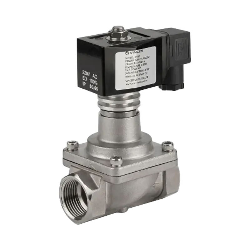
The battery industry’s move from semi-automated pilot lines to lights-out gigafactories is forcing a parallel evolution in how valves are actuated and monitored. Manual valves —such as flanged butterfly valves and wafer butterfly valves are stillstill common in older plants and pilot facilities need operators to physically walk the line to open, close, or throttle flow at each process adjustment. This model cannot keep up with the speed and repeatability demands of high-volume cell manufacturing.
Pneumatic actuators dominate battery production for two reasons. They are inherently spark-free, so they are safe for ATEX-classified zones without extra protection circuits. And they cost the least per actuation point. Process lines rely heavily on a wide variety of these automated units, including pneumatic wafer and flanged butterfly valves for large-scale solvent handling, as well as pneumatic 3-piece stainless steel ball valves, pneumatic tri-clamp ball valves, and pneumatic sanitary ball valves for precise slurry and electrolyte isolation. A rack of pneumatic solenoid valves a valve terminal can control dozens of process valves from a single fieldbus node, with response times under 100 milliseconds. The downside: pneumatic actuators consume compressed air continuously. A leaky fitting anywhere in the air distribution network represents a hidden operating cost that compounds 24 hours a day.
Electric actuators are gaining ground in non-classified areas especially on larger valves (DN100 and above) where torque requirements exceed what a compact pneumatic actuator can deliver. Electric actuators provide continuous position feedback, typically ±0.5 percent of span, enabling the closed-loop flow control that pneumatic on-off valves cannot achieve. This matters most on services like cooling water flow to formation cabinets, where precise, modulated flow control directly impacts temperature uniformity and cell quality consistency.
The next step already running in the most advanced gigafactories integrates valve diagnostics into the factory’s SCADA system via IO-Link or fieldbus protocols. An intelligent valve terminal now monitors each connected valve’s cycle count, stroke time, and end-position detection in real time. It flags a valve whose stroke time has increased by 20 percent a sign of seal wear or rising friction before the valve fails in service. This shifts maintenance from reactive (fix it when it breaks) to predictive (replace it during the next scheduled downtime). The result: higher overall equipment effectiveness in an industry where every percentage point of yield improvement means millions of dollars in annual savings.
For engineers specifying the fluid control infrastructure of a new battery production line, the takeaway is straightforward: evaluate the valve and actuator supply chain as rigorously as the coating and stacking equipment. A manufacturer with broad in-house capability across manual valves, electric actuated valves, pneumatic actuated valves, and globe control valves one that delivers material certifications, ATEX documentation, and custom actuation configurations from a single source reduces both procurement workload and the integration risk of juggling multiple component suppliers with incompatible communication protocols and lead times.
- Spark-free for ATEX-classified zones
- Lowest cost per actuation point
- Response times under 100 ms
- Continuous position feedback ±0.5%
- DN100+ torque capacity
- Closed-loop flow control
Quality at Scale Why Every Component Counts
Battery manufacturing quality follows the 1:10:100 rule familiar to every production engineer. Catch a defect at incoming inspection: $1 to fix. Catch the same defect at end-of-line testing: $10. Let it reach the customer: $100 or far more, if it triggers a field recall involving thousands of battery packs.
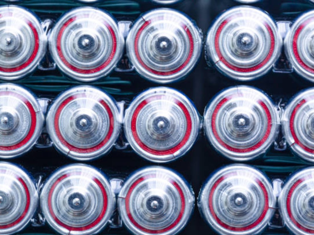
The quality control framework rests on three pillars. Incoming quality control (IQC) verifies raw materials metal foil thickness and surface finish, electrolyte purity and water content, separator porosity and tensile strength before they enter production. In-process quality control (IPQC) monitors critical parameters at every station: slurry viscosity before coating, coating thickness after drying, electrode alignment during stacking, fill weight during electrolyte dispensing. Outgoing quality control (OQC) subjects every finished cell to capacity, internal resistance, and leakage testing.
But a fourth pillar matters just as much and gets far less attention: the reliability of the support systems that make production possible. A diaphragm valve on the electrolyte filling station that drips even intermittently produces cells with insufficient electrolyte. Those cells form an incomplete SEI layer. Six months into field service, capacity fade accelerates. The failure chain is long. The root cause is obscure. The commercial consequence is the same every time: warranty costs, customer dissatisfaction, reputational damage.
At gigawatt-hour scale, the gap between 95 and 98 percent first-pass yield is not three percentage points. It is tens of thousands of additional good cells per day millions of dollars in annual revenue with zero additional capital investment. Closing that gap means treating every component in the production line as a contributor to quality. That includes the valves, actuators, sensors, and controllers too often dismissed as commodity afterthoughts. The factories that internalize this principle will be the ones that win the global race to manufacture better batteries, at higher yield, at lower cost.
المراجع
- PEM RWTH Aachen / VDMA. “Battery Cell Production Guide” (5th Edition). Available at: https://www.pem.rwth-aachen.de/
- Attia, P.M. et al. “Challenges and opportunities for high-quality battery production at scale.” Nature Communications, 2025. Available at: https://www.nature.com/articles/s41467-025-55861-7
- Kampker, A., Heimes, H. et al. “Approach for Data-Based Optimization in Cell Finishing of Battery Production.” CPSL Conference, 2023. Available at: https://www.repo.uni-hannover.de/handle/123456789/13600
- BatteryDesign.net. “Formation & Aging.” Available at: https://www.batterydesign.net/manufacture/cell-manufacturing/battery-cell-manufacturing-process/formation-aging/
- Festo AG. “Automation for Battery Manufacturing.” Available at: https://www.festo.com/cn/en/e/solutions/industry-segments/electronics-industry/battery-manufacturing-id_6949/
- Emerson Electric. “Lithium-Ion Battery Manufacturing Solutions.” Available at: https://www.emerson.com/en/corporate/industries/chemical/specialty-chemical/lithium-ion-battery-manufacturing
- GEMÜ Group. “Valve Solutions for Mixing Electrode Slurries in Li-ion Cell Manufacturing.” ValveUser, 2022. Available at: https://www.valveuser.com/show-article.asp?id=3773
- Meech International. “Industry specialist warns of the common threat of contamination in EV battery production.” Renewable Energy Magazine, 2025. Available at: https://www.renewableenergymagazine.com/storage/industry-specialist-meech-warns-of-the-common-20250411
- Coesia Group. “Integrated Solutions for Battery Cell Manufacturing Lines.” 2026. Available at: https://www.coesia.com/en/news/integrated-solutions-for-battery-cell-manufacturing-lines
- E-Mobility Engineering. “Battery Cell Manufacturing: From Coin Cells to Large-Scale Production.” Available at: https://www.emobility-engineering.com/battery-cell-manufacturing/
- VINCER Valve. Electric Actuated Valves. Available at: https://www.vincervalve.com/electric-actuated-valve/
- VINCER Valve. Globe Control Valves. Available at: https://www.vincervalve.com/vincer-globe-control-valves/
- VINCER Valve. Homepage. Available at: https://www.vincervalve.com/