
The Battery Manufacturing Process: A Three-Stage Equipment Landscape
Battery manufacturing is not one machine it is a coordinated chain of over 50 individual process steps spread across three distinct production stages, each demanding its own specialized equipment. Understanding this three-stage framework is the prerequisite to making informed equipment decisions, whether you are planning a new production line or upgrading an existing facility.
The three stages break down by capital investment roughly as follows: electrode manufacturing accounts for approximately 40% of total equipment cost, cell assembly takes roughly 30%, and formation and testing commands the remaining 30% (PEM RWTH Aachen, 2024). This is not a marginal industry the global battery manufacturing equipment market stood at $15.6 billion in 2025 and is projected to reach $36.9 billion by 2030, growing at a compound annual rate of 18.8%, driven by electric vehicle adoption and grid-scale energy storage demand (Research and Markets, 2025).
Think of it like automotive manufacturing: the electrode stage is the engine block casting get it wrong and nothing downstream can fix it. Cell assembly is the final assembly line where components come together. Formation and testing is the quality inspection and road test. Each stage depends on the one before it, and each has equipment decisions that lock in your production capabilities for years.
There is one equipment category, though, that cuts across all three stages from slurry mixing to electrolyte filling to vacuum drying and gets almost no attention in battery equipment guides: valves and fluid control systems. More on that below.
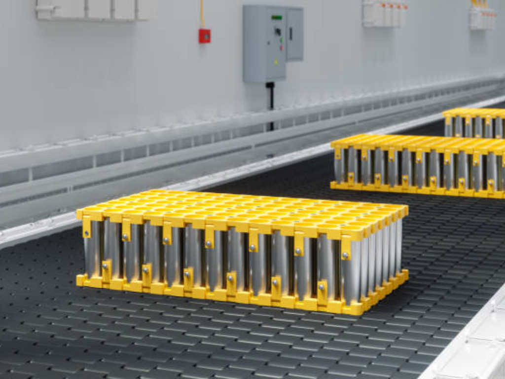
Electrode Manufacturing Equipment: Where Cell Quality Begins
Electrode quality is determined upstream if the slurry is not right, no amount of precision downstream can fix it. The three equipment stages in electrode manufacturing form a quality chain where each step either amplifies or corrects the previous one, starting with the mixer.
Mixing Equipment: The Foundation of Electrode Quality
Mixing is where battery performance is born or lost. Active materials, conductive additives, polymer binders, and solvents must be dispersed into a homogeneous slurry with precise solid content typically 65 75% for NMC cathodes and 50 60% for LFP cathodes. Dispersion fineness must stay below 15 microns; larger agglomerates create coating defects that propagate into cell failure.
The equipment choice here has significant energy implications that most buyers overlook. Traditional planetary mixers consume roughly 8,000 kWh per batch. Newer hydrodynamic shear mixing technology such as the Eirich MixSolver can achieve the same dispersion quality at approximately 400 kWh, a 95% reduction in energy consumption. Over the lifetime of a production line running three shifts, that difference alone can exceed the purchase price of the mixer itself.
A typical mixing cycle runs 2-3 hours: 10-30 minutes of dry mixing, 30 60 minutes of kneading, and 60-120 minutes of final dispersion. Batch-to-batch consistency here is the first gatekeeper of cell uniformity.
95% energy reduction Switching from a traditional planetary mixer (8,000 kWh/batch) to a hydrodynamic shear mixer like the Eirich MixSolver (400 kWh/batch) cuts energy consumption by 95%. Over a three-shift production line lifetime, that saving alone can exceed the mixer’s purchase price.
Coating and Drying Equipment: The Most Energy-Intensive Step
Coating and drying is where the capital budget and the energy bill collide. This single step accounts for roughly 15% of total manufacturing cost but consumes over 75% of the production line’s total energy (PEM RWTH Aachen, 2024). The dominant technology is slot-die coating: a precision extrusion head that deposits slurry onto aluminum or copper current collector foil. On a production line, coating speeds range from 20 to 80 meters per minute.
The precision requirements are punishing: coating thickness tolerance must stay within ±2 microns, and areal density deviation must remain under ±1.5%. Behind the coating head sits a drying oven stretching 60 100 meters, with electrical heating units drawing between 1,058 and 2,292 kW depending on line speed and width. Modern lines increasingly integrate closed-loop NMP solvent recovery systems that can reclaim over 90% of the solvent both an environmental compliance requirement and a meaningful operating cost reduction, as demonstrated by Dürr Group’s production line installations across European gigafactories.
For procurement teams, the coating-drying system is the single largest equipment decision in the electrode stage: it defines your maximum line speed, your energy cost per kWh of cell output, and your coating quality ceiling.
Calendering and Slitting Equipment: Precision at Speed
After drying, the coated electrode passes through a calendering roller press that compresses the material layer to its target density typically 3.4-3.7 g/cm³ for NMC cathodes and 1.5-1.7 g/cm³ for graphite anodes. The goal is to achieve 25-35% porosity: too dense and electrolyte cannot penetrate; too loose and electronic conductivity suffers.
The calendered electrode roll then enters the slitting machine, where rotating blades or laser systems cut it into narrow strips at 50-100 meters per minute. Width tolerance must stay within ±0.3 mm, and critically burr height on the cut edge must remain below 10 microns. A burr exceeding this threshold can puncture the separator during cell assembly, creating an internal short circuit and a safety risk that no amount of end-of-line testing can reliably catch.
Cell Assembly Equipment: Winding, Stacking, and the Filling Challenge
The single biggest equipment decision in cell assembly is winding versus stacking and the answer depends entirely on your cell format. Cylindrical cells demand winding; pouch cells demand stacking; prismatic cells sit in the middle, where the choice defines your production speed, yield rate, and cost structure.
Winding vs Stacking: The Defining Equipment Choice
Winding machines take continuous strips of anode, separator, and cathode and roll them into a cylindrical or flattened “jelly roll.” The technology is mature and blisteringly fast: state-of-the-art cylindrical winders from manufacturers like Yinghe Technology and Han’s SLE exceed 260 pieces per minute (PPM), while prismatic winders operate at 24-40 PPM. Tension control during winding must maintain ±0.5N precision any fluctuation causes electrode misalignment that degrades capacity and cycle life.
Stacking machines, by contrast, layer individual sheets of anode, separator, and cathode in alternating sequence the “Z-stacking” method being the dominant approach for pouch cells. Stacking speed has improved dramatically, with current-generation equipment achieving 0.15-0.39 seconds per sheet. The key advantage of stacking is higher space utilization inside the cell and lower internal stress, which translates to longer cycle life particularly important for EV and energy storage applications where warranty periods stretch to 8-10 years.
The practical decision framework is straightforward: if you are making cylindrical cells at high volume, winding is the only viable choice. If you are making pouch cells, stacking is mandatory. For prismatic cells, the trade-off is speed (winding wins) versus cycle life and energy density (stacking wins). Many large manufacturers run both technologies on different lines.
Speed Benchmarks by Cell Format
-
Cylindrical: 260+ PPM (Winding · Turret)
-
Prismatic: 24-40 PPM (Winding or Stacking)
-
Pouch: 154-400 PPM equiv. (0.15-0.39 s/pc · Z-Stacking)
Electrolyte Filling and Assembly: Precision in Controlled Environments
The assembly chain inserting the electrode package into the cell casing, laser-welding the tabs and terminals, injecting electrolyte, and hermetically sealing all takes place inside dry rooms where the dew point is maintained between -50°C and -80°C. At these humidity levels, the air contains less than 1 part per million of water vapor. A single drop of sweat contains enough moisture to destroy an entire batch of cells.
Electrolyte filling is the most sensitive step: the precise volume of electrolyte typically lithium hexafluorophosphate (LiPF ) dissolved in organic carbonate solvents must be dosed to within ±0.5% of the target weight under vacuum. The filling equipment itself must be constructed from materials compatible with the electrolyte’s aggressive chemistry, since any reaction with moisture produces hydrofluoric acid one of the most corrosive substances in industrial use.
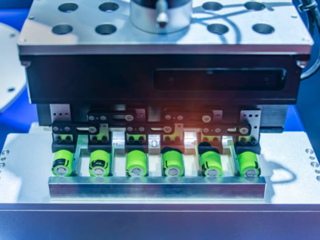
Formation and Testing: The Costliest Bottleneck in Battery Production
Formation the initial charge-discharge cycling that builds the solid electrolyte interphase (SEI) layer on the anode is the single most time-consuming step in battery manufacturing, taking 1.5 to 3 weeks depending on cell chemistry and capacity. This is also the most expensive step, representing approximately 32.6% of total manufacturing cost (PEM RWTH Aachen, 2024). The SEI formation consumes 5-10% of the cell’s initial lithium inventory, permanently reducing capacity but without it, the cell would degrade catastrophically within the first few cycles.
Aging follows formation: cells are held at elevated temperature to accelerate side-reaction stabilization, and those with abnormal self-discharge rates are identified and removed. Finally, grading equipment measures every cell’s capacity and internal resistance, sorting them into bins where capacity deviation within a single grade must stay below 1%. This consistency is what makes a battery pack perform reliably one weak cell in a series string drags down the entire pack.
The formation and testing stage is the hardest to accelerate with capital spending alone. While you can buy faster coaters and winders, formation time is fundamentally constrained by electrochemistry. The industry’s current focus is on simultaneous multi-cell formation cabinets and predictive algorithms that can shorten aging time by identifying stabilized cells earlier.
The Overlooked Essential: Valves and Fluid Control in Battery Manufacturing
When people picture battery manufacturing equipment, they imagine coating machines and winding lines. But running through every stage from slurry mixing to electrolyte filling to vacuum drying is a hidden network of thousands of valves and actuators that control the flow, pressure, and purity of every material that enters a battery cell. A single gigafactory can contain over 5,000 control valves (Festo, 2025), and at Northvolt’s Ett gigafactory in Sweden, more than 1,000 pneumatic actuators were installed on process valves across the production line (Rotork, 2024).
5,000+ control valves per gigafactory 1,000+ actuators at Northvolt | 50 smart positioners
Valve Types and Their Roles Across the Battery Production Line
Different stages demand different valve configurations. In slurry mixing, ball valves paired with quarter-turn pneumatic actuators and sensor boxes meter active materials, binders, and solvents into the mixer according to precise recipe quantities. Pre-assembled butterfly valve units are a common sight in this section. In electrolyte filling, diaphragm and pinch valves handle the precision dosing chosen for their zero-contamination design and chemical resistance, they dispense exact electrolyte volumes into cells under vacuum. In the drying and vacuum sections, butterfly valves regulate chamber evacuation while proportional pressure regulators control vacuum levels precisely to cut energy use. For corrosive chemical dosing in cathode material production, angle seat valves handle the fast open-close cycles.
The actuators driving these valves are predominantly pneumatic quarter-turn designs with spring-return or double-acting configurations for fail-safe operation. Smart positioners provide digital proportional control where process precision demands it.
What Makes a Valve “Battery-Grade”: Material Compatibility and Selection
Industrial valves are not automatically suitable for battery production lines. Three requirements separate battery-grade valves from general-purpose industrial valves: material purity, environmental compatibility, and certification.
The most critical material constraint is absolute prohibition of copper and zinc. These metals, common in standard pneumatic components and aluminum alloy die-cast parts, can shed microscopic particles that contaminate electrode materials and cause internal short circuits. Instead, battery-grade valves demand stainless steel 316L, PTFE (Teflon), PVDF, or PPGF (polypropylene glass fiber) construction. The performance gap is substantial: PVDF V-port control ball valves offer 100 times the abrasion resistance of PTFE-lined metal alternatives in corrosive chemical dosing applications, while PPGF ball valves provide 30 times the abrasion resistance for slurry handling. For dry-room environments, even the valve lubrication matters standard grease loses lubricity below -20°C, while low-dew-point specialty greases maintain performance down to -80°C. ATEX explosion-proof certification is mandatory for any valve installed in electrolyte filling and formation areas, where flammable solvent vapors create an ignition risk.
For procurement teams sourcing valves for battery production lines, working with manufacturers that hold ISO 9001, CE, and SIL certifications and offer 50-plus material options including 316L stainless steel, PTFE, and PVDF for copper-free and zinc-free environments eliminates months of supplier vetting. The ability to customize valves across 10 functional dimensions, from temperature rating to explosion-proof configuration to switching speed, means a single supplier specification can cover the full production line rather than forcing separate procurement tracks for different process stages.
How to Evaluate Battery Manufacturing Equipment Suppliers
After understanding what equipment you need, the next question is who to buy it from and the cheapest quote is rarely the cheapest option over the equipment’s lifetime. A structured evaluation framework prevents the most common procurement mistake: comparing only purchase prices while ignoring total cost of ownership.
Start with technical capability verification: does the supplier cover the full process chain you need, or will you have to stitch together equipment from multiple vendors and manage the integration yourself? Request factory acceptance testing (FAT) with simulated load conditions and performance data logs before shipment a supplier that refuses FAT is a red flag regardless of price. Check certifications: ISO 9001 is the quality management baseline, IATF 16949 adds automotive-grade rigor, and CE marking confirms EU safety compliance. For valves and actuators specifically, SIL (Safety Integrity Level) certification provides independent verification of reliability in safety-critical applications.
Delivery reliability separates professional suppliers from opportunistic ones. Standard production line equipment should ship within 45 60 days of order confirmation; on-time delivery rates below 95% signal systemic issues. Contract structure matters equally: the industry-standard payment schedule is 30% deposit, 60% before shipment after FAT approval, and 10% after site acceptance testing (SAT) this protects both parties and aligns incentives.
Finally, evaluate the supplier’s after-sales capability before you need it. A production line stoppage costs far more than any equipment discount. Can the supplier provide remote diagnostics within hours? Do they maintain regional spare parts inventory? An engineering team with over a decade of application experience and a documented 12-hour response commitment turns a production emergency into a manageable disruption.
Before You Sign: 5-Point Supplier Check
-
FAT with load simulation: Require factory acceptance testing with simulated load conditions and performance data logs before shipment.
-
ISO 9001 + CE + SIL certifications: Verify quality management, EU safety compliance, and safety integrity level for valves and actuators.
-
95% on-time delivery: Standard lead times of 45 60 days; on-time delivery rates below 95% signal systemic issues.
-
30/60/10 payment structure: 30% deposit, 60% pre-shipment after FAT, 10% after site acceptance testing (SAT).
-
12h remote diagnostic response: An engineering team with over a decade of application experience that responds within 12 hours.
For battery manufacturers planning new production lines or upgrading existing facilities, a free technical consultation on valve and actuator specifications covering media compatibility, pressure ratings, connection standards, and material selection across 50-plus material options can be arranged within 12 hours. Discuss your battery production line requirements with an engineering team at VINCER Valve.
Spec Your Battery Production Line’s Valve Requirements Free technical consultation covering media compatibility, pressure ratings, material selection across 50+ options, and connection standards with a response within 12 hours. Request a Consultation.
References
-
Research and Markets. “Battery Manufacturing Equipment Market Global Forecast to 2030.” 2025.
-
PEM RWTH Aachen. “Lithium-Ion Battery Cell Production Process Guide.” 2024.
-
Festo. “Automation for Battery Manufacturing.” 2025.
-
Rotork / Eltav. “Green Battery Factory in Sweden Supported by Rotork Actuators.” 2024.
-
Emerson Automation Experts. “Control Valve Considerations in Lithium Battery Applications.” 2024.
-
VINCER Valve. “Certifications.”
-
VINCER Valve. “Contact for a Quote.”
-
VINCER Valve. Homepage.
 English
  French
  Spanish
  Italian
  German
  Dutch
Dutch  Portuguese
  Korean
  Russian
  Chinese
  Finnish