
Turning raw powders into the most expensive component of an electric vehicle is a feat of precision engineering that few outside the industry fully grasp. A modern lithium-ion battery cell passes through over 50 individual processes before it’s ready for a vehicle and every one of them is a potential failure point that can compromise safety, performance, or yield. Here’s how it works, stage by stage.
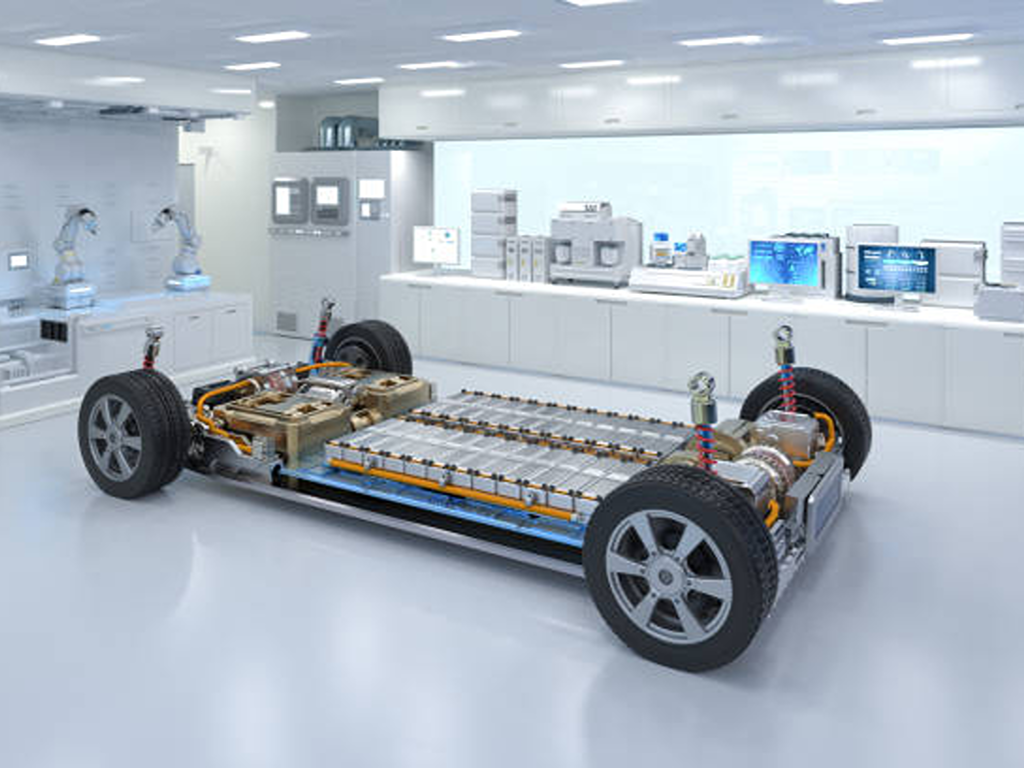
Raw Materials That Go Into an EV Battery
Before any machine starts running, the recipe has to be right. An EV battery cell is built from four core material categories, each with a distinct electrochemical role.
The cathode the positive electrode is where lithium ions nest during discharge. Two chemistries dominate: NMC (LiNixMnyCozO2), prized for its energy density, and LFP (LiFePO4), valued for cost and thermal stability. The anode the negative electrode is almost universally graphite, with natural graphite offering lower cost and synthetic graphite delivering a higher first-cycle coulombic efficiency (~95% vs ~90%).
Between them sits the separator, a microporous polypropylene or polyethylene membrane just 10-25 microns thick. Its porosity of 40-50% lets lithium ions pass freely while keeping electrodes electrically isolated and its thermal shutdown temperature (~130°C) acts as a built-in safety fuse. The fourth component, the electrolyte, is a 1M solution of lithium hexafluorophosphate (LiPF6) dissolved in a blend of organic carbonates (EC/DMC/EMC), serving as the highway for ions shuttling between cathode and anode.
Think of it as a cake recipe: cathode = flour (the bulk), anode = sugar (the pairing), electrolyte = water (the medium), and separator = baking paper (the barrier). The recipe dictates every subsequent step.
Electrode Manufacturing From Powder to Precision Foil
Electrode manufacturing accounts for roughly 40% of a production line’s capital cost and for good reason. This is where micron-scale powders are transformed into precision films whose uniformity determines everything downstream. The essence of electrode manufacturing is deceptively simple: it’s the most “printing-like” stage in battery production, and the first major yield gate.
Note: Electrode manufacturing accounts for ~40% of total production line CapEx and nearly half of total energy consumption get this stage wrong, and every subsequent step compounds the error.
Slurry Mixing The Foundation of Electrode Quality
Mixing is where battery quality begins or ends. Active material powders, conductive carbon additives, and polymer binders are combined with solvent in precise proportions to form a homogeneous slurry. The target viscosity typically falls between 2,000 and 10,000 centipoise for cathode formulations, with solid content at 60-75%.
This isn’t simple stirring. For high-nickel cathodes (Ni ≥ 0.8), moisture sensitivity demands mixing rooms with dew points at or below -40°C a single droplet of ambient humidity can corrode the aluminum current collector before coating even begins. Traditional planetary mixers process batches over 2-6 hours, while twin-screw continuous extrusion systems reduce residence time to 30-120 seconds with better reproducibility and less downtime (Volta Foundation, 2024).
The scale of fluid handling is staggering: a single gigafactory deploys upward of 5,000 automated control valves across its slurry production infrastructure, each responsible for precise dosing of ingredients into mixing vessels (Mobility Engineering Tech, 2024).
Coating and Calendering Achieving Micron-Level Uniformity
Once mixed, the slurry is applied to metal foil current collectors aluminum for the cathode, copper for the anode using slot-die coating. This is the single most energy-intensive step in battery manufacturing, consuming approximately 48% of total production energy.
In a representative high-speed line, copper foil just 6 microns thick and 4,000 meters long travels through the coater at 80 meters per minute. The freshly coated foil then passes through a flotation dryer up to 70 meters long, where temperatures ramp from ambient to 150°C, evaporating the solvent. But speed comes with a trade-off: coatings dried at 150°C show binder concentrations at the surface layer three times higher than at the substrate a migration effect that can degrade adhesion and electrochemical performance (Volta Foundation, 2024).
After drying, the coated foil enters a calendering press essentially a pair of heated rollers that compress the electrode to its target density and porosity (typically 25-35% for cathodes, 30-40% for anodes). Higher pressure increases volumetric energy density but simultaneously raises tortuosity, which impedes lithium-ion transport. Coating thickness deviation beyond ±2% is typically rejected a tolerance tighter than most precision machining operations.
Coating thickness tolerance: ±2%Tighter than most precision machining operations. Deviation beyond this threshold is rejected electrode uniformity is the first yield gate.
Key Electrode Manufacturing Parameters
| Parameter | Cathode | Anode |
| Foil material | Aluminum (10-20 μm) | Copper (6-10 μm) |
| Target porosity | 25-35% | 30-40% |
| Mixing viscosity | 2,000 – 10,000 cP | 1,000 – 5,000 cP |
| Drying temperature | RT – 150°C | RT – 150°C |
Slitting and Electrode Making Cutting to Cell-Ready Size
The jumbo rolls now need to be cut to cell dimensions. Slitting machines reduce the wide coated foils into narrow strips, and any burr or buckling introduced here creates a pathway for internal short circuits one of the primary root causes of thermal runaway in finished cells. The industry standard requires burr height below 50% of the coating thickness.
Following slitting, electrode-making machines integrate tab cutting, tab welding (ultrasonic for copper and aluminum tab-to-collector connections, laser for top-cap sealing), and protective taping. Optical inspection systems scan every electrode edge at micron resolution before the sheets proceed to assembly.
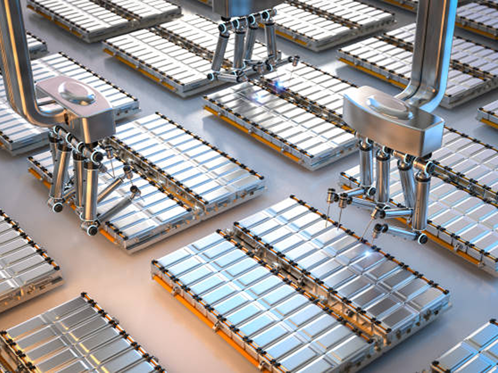
Cell Assembly Building the Battery Core
With electrodes ready, the manufacturing process reaches its physical heart: assembling the anode-separator-cathode stack into a functional cell. This is also the structural fork in the road the point where the cell’s final form factor (cylindrical, prismatic, or pouch) is decided.
The choice between stacking and winding is the first design decision. Cylindrical cells almost exclusively use winding (fast, economical), pouch cells favor Z-stacking (higher precision, fewer internal voids, better energy density), and prismatic cells can use either. Modern high-speed stacking machines achieve cycle times under 0.1 seconds per piece with yields above 99.5% a level of throughput that has made stacking commercially viable even at gigafactory scale.
-
Winding: Faster and cheaper, but curved edges create wasted volume.
-
Stacking: Higher energy density and better thermal behavior, but historically slower. Modern high-speed stacking has narrowed the throughput gap significantly.
All of this takes place in dry rooms where the dew point is held at -55°C and relative humidity hovers around 0.08% ISO Class 7 cleanroom conditions. Moisture at this stage would react with the electrolyte precursor materials, forming hydrofluoric acid that etches the electrodes from the inside out.
Electrolyte Filling and Sealing The Precision Wet Step
If electrode manufacturing is printing, electrolyte filling is surgery. The assembled but dry cell is placed under vacuum (absolute pressure below 10 millibar), and a precisely metered dose of electrolyte is injected. The fill volume must be accurate to within ±1% too little, and dry spots create localized resistance and lithium plating; too much, and the cell swells or leaks.
The electrolyte itself demands extreme purity: LiPF6 concentration at 1M, water content below 10 parts per million. Fast-cycling angle seat valves rated for millions of cycles control the fill and vacuum pulses, while all wetted components must be PVDF or PTFE to prevent metal ion leaching into the electrolyte (Mobility Engineering Tech, 2024). After filling, the cell is vacuum-sealed, and the assembly stage is complete.
Dry room conditions: -55°C dew point, 0.08% relative humidity, ISO Class 7. Moisture at this stage forms hydrofluoric acid that etches electrodes from the inside out.
Formation, Aging, and Finishing Bringing the Cell to Life
A freshly assembled cell is chemically inert it has never held a charge. Formation is its first electrochemical breath. During the initial charge cycle, a portion of the electrolyte solvent (typically ethylene carbonate) reductively decomposes at the anode surface, forming a solid electrolyte interphase (SEI) layer just 5-20 nanometers thick. This layer is lithium-ion-conductive but electronically insulating it passivates the anode, preventing further electrolyte decomposition on every subsequent cycle.
The price of this protective layer is irreversible capacity loss. Graphite anodes typically lose 5-10% of their initial capacity to SEI formation, reflected in a first-cycle coulombic efficiency of 90-95%. Everything the cell will ever deliver starts from this reduced baseline.
After formation, cells enter aging a waiting period of one to three weeks at controlled temperatures (25-45°C) that allows electrolyte to fully permeate the electrode pores and cell voltage to stabilize. During this time, formation gases (primarily ethylene, hydrogen, and CO2 are vented through a degassing step, after which the cell is permanently resealed. Formation racks and degassing stations operate under precise thermal control (±1°C), because SEI quality and therefore battery lifetime is temperature-sensitive down to the single degree.
Process Timeline:
-
Formation: First charge forms SEI layer
-
Aging: 1-3 weeks: permeation & stabilization
-
Degassing: Vent gases, final seal
-
EOL Testing: 30+ parameter check
Precision Fluid Control The Hidden Backbone of Battery Production
Walk through any gigafactory and you’ll notice thousands of pipes, valves, and actuators woven through every production stage. A single slurry production line alone uses upward of 5,000 control valves making fluid control components the most numerically abundant precision devices in the plant, yet the least discussed in manufacturing literature (Mobility Engineering Tech, 2024).
Valves in Slurry Mixing and Electrode Processing
The slurry mixing station is where valve density peaks. Every powder, every solvent, every additive enters the mixing vessel through a dedicated flow path controlled by automated valves. V-port ball valves handle precise metering and dosing their characterized flow profile (FL ~ 0.9) provides globe-valve-like precision in a compact package. Butterfly valves manage bulk liquid and slurry transfer in pipes 2 inches and larger, where their cost-effectiveness at scale makes them the default choice.
But the valve material is just as critical as the valve type especially in cathode precursor production. The wet process for cathode materials involves highly corrosive fluids: sulfuric acid, caustic soda, ammonia, and sulfates of nickel, cobalt, and manganese. Any iron oxide, zinc, asbestos, or PVC leached from valve or piping materials will irreversibly contaminate the cathode precursor blend. This is why thermoplastic valves have become the standard: PPGF (polypropylene glass fiber) offers 30 times the abrasion resistance of PTFE-lined metal, while PVDF (polyvinylidene fluoride) provides 100 times the abrasion resistance of PTFE along with superior chemical inertness (SAFI / ValveUser, 2024).
5,000+ Control Valves Per GigafactoryEach responsible for precise dosing of powders, liquids, and slurries into mixing vessels making fluid control the most numerically abundant precision system in any battery plant.
Valves in Electrolyte Handling and Thermal Management
Downstream, electrolyte filling demands a different valve profile entirely. Angle seat valves dominate here their fast open/close response and compact integrated actuation make them ideal for the rapid vacuum-and-fill pulse cycles at filling stations, and their rated lifetime (millions of cycles) matches the relentless pace of a high-throughput production line.
The formation and aging stage introduces yet another fluid-control challenge: thermal regulation. Maintaining ±1°C stability across hundreds of formation channels requires modulating control valves on jacketed cooling circuits globe control valves with positioner feedback providing the fine-grained flow adjustment that SEI formation quality depends on.
The valve selection decision at each stage is not trivial. The table below summarizes the typical mapping:
Valve Type Selection by Battery Manufacturing Stage
| Manufacturing Stage | Fluid / Media | Recommended Valve Type | Key Requirement |
| Slurry mixing (powder/liquid dosing) | Active materials + solvents | V-port ball valve | Precision metering (FL ~ 0.9) |
| Slurry mixing (bulk transfer ≥ 2″) | Slurries + process liquids | Butterfly valve | Cost-effective at scale |
| Electrolyte filling | LiPF6 electrolyte | Angle seat valve | High cycle life + chemical inertness |
| Cathode wet process | H2SO4 / NaOH / NH3/ metal sulfates | Thermoplastic ball/pinch valve (PPGF/PVDF) | Zero metal contamination |
| Thermal management (formation/aging) | Cooling water/glycol | Globe control valve | ±1°C regulation |
Quality Assurance Testing at Every Stage
Quality in battery manufacturing is not a final checkpoint it’s embedded at every stage because defects compound downstream. An electrode coating defect missed at slitting becomes a short-circuit risk in the assembled cell. A weak tab weld becomes a hot spot under load. A poorly formed SEI becomes an early-life capacity fade.
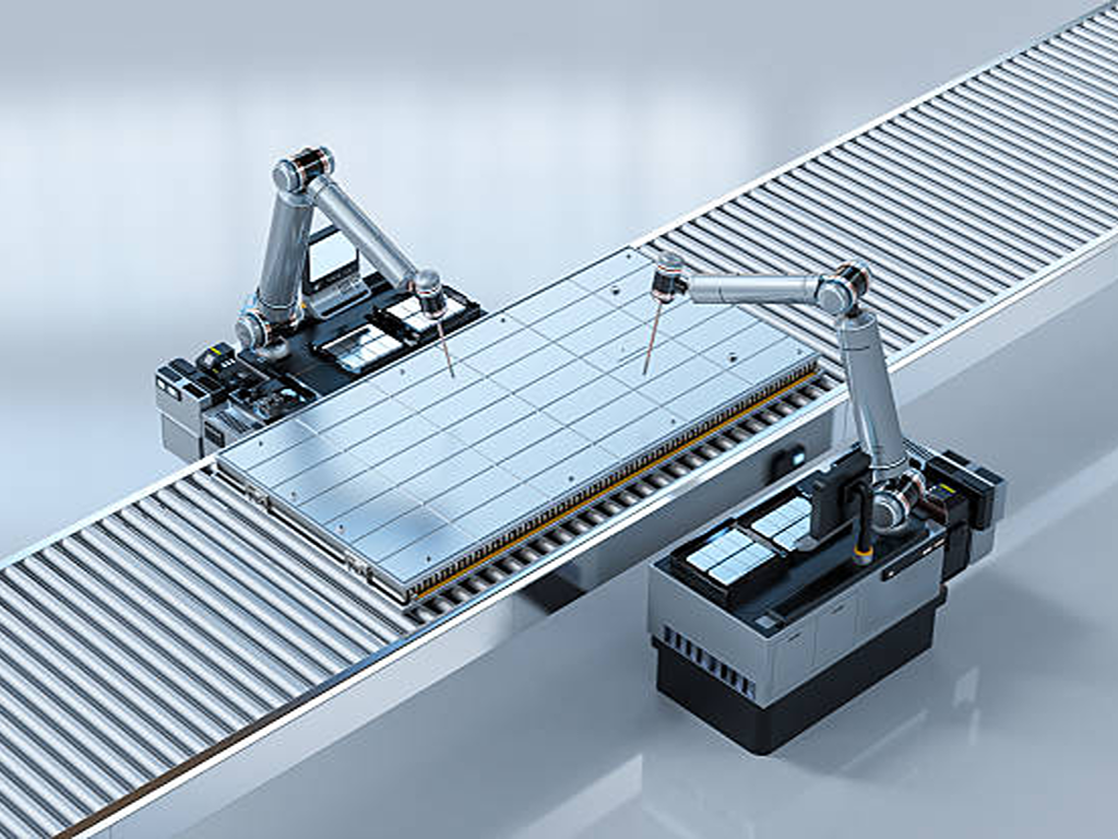
Optical inspection systems scan electrode edges at micron resolution. Ultrasonic weld peel-strength tests verify tab-to-collector bond integrity. Helium leak detection sensitive to 10-5 mbar·L/s confirms hermetic sealing after electrolyte filling. Electrochemical impedance spectroscopy (EIS) probes for internal defects that visual inspection cannot catch. By the time a cell reaches end-of-line testing, it has cleared over 30 individual parameter checks: capacity, voltage, internal resistance, self-discharge rate, insulation resistance, thickness, and weight, among others.
Full traceability ties it all together. Every cell carries RFID or barcode data linking it to the specific slurry batch, coater lane, winding station, filling nozzle, and formation rack that produced it a digital thread that makes root-cause analysis possible when something goes wrong, and a non-negotiable requirement for any modern gigafactory.
For battery manufacturers specifying fluid control components across their production lines, working with a supplier that offers in-house R&D, design, testing, and assembly under one roof can simplify the valve selection process. VINCER provides ball valves for precise metering, globe control valves for temperature regulation, and multi-material options including stainless steel, duplex, and PTFE/PVDF-seated configurations with tailored selection support to match the chemical and precision demands of each manufacturing stage. Explore VINCER’s ball valve series or discuss your specific requirements.
Discuss Your Valve Requirements for Battery Production
Our engineering team provides tailored selection support for every manufacturing stage from slurry mixing to thermal management. Request a Consultation
References
-
Volta Foundation. “Battery Manufacturing Basics from CATL’s Cell Production Line (Part 1).” 2024. volta.foundation
-
Mobility Engineering Tech. “Control Valves: Essential Components for EV Battery Manufacturing and Recycling.” 2024. mobilityengineeringtech.com
-
SAFI / ValveUser. “The Right Choice of Valves in the Wet Section of Battery Production for Electric Vehicles.” 2024. valveuser.com
-
VINCER Valve. Ball Valve Series. vincervalve.com
-
VINCER Valve. Globe Control Valves. vincervalve.com
-
VINCER Valve. Contact for a Quote. vincervalve.com
-
VINCER Valve. Homepage. vincervalve.com
 English
  French
  Spanish
  Italian
  German
  Dutch
Dutch  Portuguese
  Korean
  Russian
  Chinese
  Finnish