Selecting the right directional control valve is the line of demarcation between a seamless pneumatic system and a catastrophic lock-up. When evaluating a 2 way vs 3 way solenoid valve, understanding mechanical differences, flow paths, and exhaust logic is paramount for optimizing efficiency and preventing actuator wear.
Understanding the Core Difference: Ports, Flow Paths, and P&ID Symbols
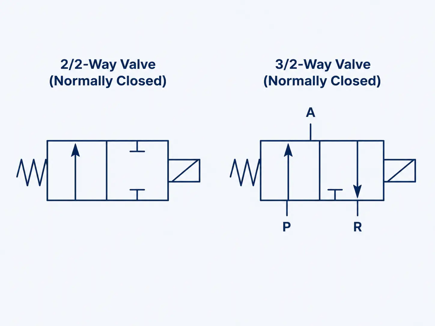
The rigorous selection process begins with dissecting the precise difference between 2 way and 3 way solenoid valve port architectures. In professional P&ID (Piping and Instrumentation Diagram) development, these directional control mechanisms are represented by standardized ISO 1219 symbols. A directional control valve symbol typically consists of two adjacent squares representing the two shifting positions (states) of the internal spool or poppet. The true distinction lies in the internal routing arrows and port connections mapped within these squares, identifying whether a valve supports “exhaust logic” and clearly identifying the fail-safe spring-return position assumed when electrical power is removed.
2-Way Solenoid Valves: The Binary Isolation Mechanism
A 2 way solenoid valve serves as a strict binary switch. It contains exactly two designated ports: an Inlet (Port 1) and an Outlet (Port 2). Its mechanical design is optimized purely for the isolation, release, or mass flow control of a specific liquid or gas medium. When the electromagnetic coil is energized, the internal plunger lifts (or shifts, depending on pilot assistance), directly opening the internal orifice to allow fluid passage to the outlet.
Engineering precision in 2-way valves heavily revolves around seal selection and seat design. While PTFE (Teflon) is often touted across the industry for its unparalleled chemical resistance, it remains a semi-rigid material that may struggle to conform perfectly to micro-abrasions on the metal seat. In high-precision gas applications or hazardous chemical containment, a “Soft Seat” configuration utilizing elastomers (such as NBR, EPDM, or FKM/Viton) is strictly required to achieve a “Bubble-tight” zero-leakage state. In stark contrast, “Hard Seats” featuring metal-to-metal contact are strictly reserved for extreme thermal environments, such as high-cycle continuous steam loops at 200°C, where an ANSI Class IV or V leakage rate is technically acceptable and inherent to the process parameters. By mastering these sealing dynamics, engineers can drastically extend the operational lifespan of the pipeline.
3-Way Solenoid Valves: Routing, Mixing, and Venting Dynamics
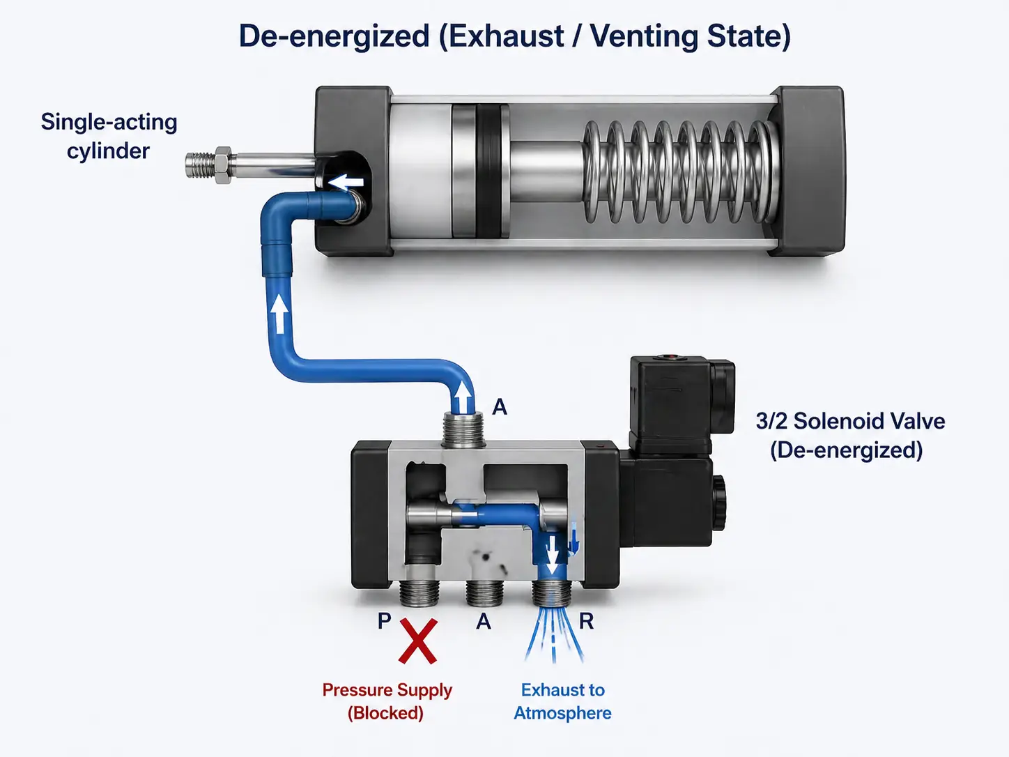
A 3 way solenoid valve introduces a critical third dimension to the fluid dynamic equation – typically designated as Port 3 or the Exhaust/Vent port. This third port is the defining factor in complex pneumatic control. It empowers the valve to not only supply high-pressure air to a mechanism but also to relieve downstream trapped pressure when the primary supply is electronically cut off. Without this continuous venting capability, any connected pneumatic actuator would remain permanently pressurized, immobilized, and incapable of executing a return stroke.
Beyond simply counting ports, engineers must evaluate the internal shifting mechanism when analyzing a 2 way valve vs 3 way valve. Solenoid valves generally utilize either a poppet or a spool design. Poppet valves use a plunger with a resilient seal that presses directly against an orifice. They offer extremely fast response times, high flow rates, and are inherently self-cleaning, making them highly resilient against minor pipeline contaminants. Spool valves, conversely, utilize a cylindrical spool sliding within a machined bore. While spool valves excel in complex multi-way routing (often used in 4-way and 5-way configurations), they are highly susceptible to friction and require well-lubricated or meticulously filtered compressed air to prevent seal shearing over millions of cycles.
| Technical Attribute | 2-Way Solenoid Valve | 3-Way Solenoid Valve |
|---|---|---|
| Port Configuration | Inlet (1) & Outlet (2) | Inlet (1), Outlet (2), Exhaust (3) |
| ISO 1219 Logic | Normally Closed (NC) / Normally Open (NO) | Mixing, Diverting, or Venting |
| Return Mechanism | Spring-return or Assisted-lift | Universal, Mixing, or Diverting Spool/Poppet |
| Control Target | Liquid Isolation, Shut-off, Batching | Single-acting Cylinders, Pilot Circuits |
Normally Closed (NC) vs. Normally Open (NO) Configurations
Fail-safe logic dictates the definitive state of the valve during an unexpected power loss. In rigorous industrial engineering, this is not a matter of operational preference but a stringent safety mandate. When evaluating these valves, the NC or NO configuration must identically match the “safe failure” mode demanded by the process hazards analysis.
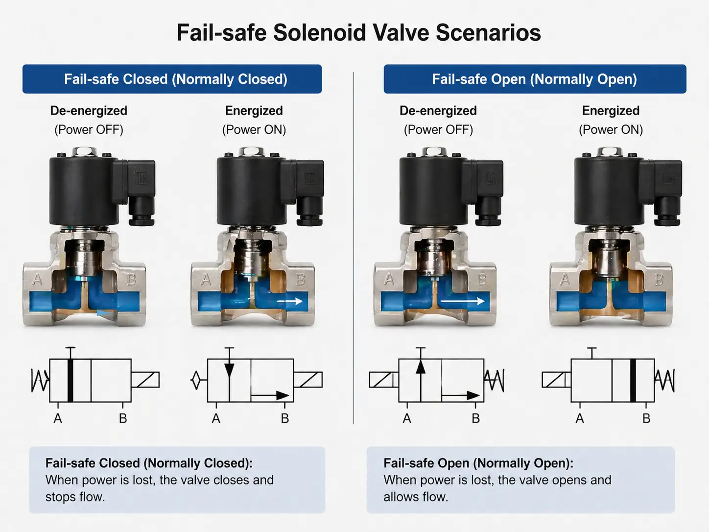
- A 2/2 Normally Open (NO) valve for Compressor Unloading: In heavy-duty air compressor circuits, a 2/2 NO valve is utilized to continuously vent the compressor head during idle states. In the event of a power failure, the electromagnetic coil de-energizes, and the internal spring forces the valve open. This guarantees that upon system reboot, the compressor motor starts against zero backpressure, effectively preventing catastrophic motor stall and electrical coil burnout.
- A 2/2 Normally Closed (NC) valve for Reactor Cooling Bypass: In aggressive chemical dosing or hazardous liquid lines, a 2/2 NC valve ensures that the pathway remains absolutely sealed during normal dormant operations. Under the ironclad physical law of an NC configuration, any loss of electrical power instantly forces the internal mechanical spring to drive the plunger down, slamming the orifice shut. This mechanically guaranteed closure completely isolates the hazard, preventing uncontrolled flooding or chemical runaway reactions without relying on secondary electrical backup systems.
For operations concerned with extreme thermal heat buildup or critical energy conservation (such as remote solar-powered oil pipelines), standard NC/NO coils – which require continuous electrical current to maintain an open or closed state – can be detrimental. In these advanced scenarios, engineers deploy bistable (latching) solenoid valves. These highly specialized components use a brief pulse of electricity to shift the internal plunger, which is then held firmly in place by a permanent magnet. To reverse the state, a pulse of reverse polarity is applied. This innovative design completely eliminates continuous coil heating, radically extending the lifespan of the valve in isolated and demanding environments.
Sizing and Flow Characteristics: Understanding the Cv Value
Before transitioning to application logic, a plant engineer must address the critical sizing paradox. The Flow Coefficient (Cv) is the universally accepted standard measuring a valve’s internal volumetric capacity to pass fluid at a specific pressure drop. It is a highly prevalent, yet deeply flawed engineering mistake to size a valve strictly based on the physical pipe thread dimensions (e.g., matching a 1/2″ NPT pipe with a 1/2″ NPT valve) rather than calculating the actual required Cv to satisfy the flow rate.
For liquids, the rigorous calculation involves specific gravity and the acceptable pressure drop. Undersizing a valve severely limits production batch speeds and chokes pneumatic actuators, while oversizing a valve leads to unnecessary capital procurement costs and erratic, unstable flow control, particularly in high-pressure differential environments where precision is non-negotiable.
Engineering Rule of Thumb for Exhaust Bottlenecks:
A 3 way solenoid valve inherently features a significantly more tortuous internal flow path (due to its complex diverting galleries) than a 2-way valve of the exact same footprint. This architectural reality often results in a 10-15% lower relative Cv value for the exhaust port. If the required exhaust speed for a fast-cycling single-acting cylinder cannot be met by a standard direct-acting valve, engineers should avoid blindly increasing the valve’s overall port size – which aggressively inflates infrastructure cost and air consumption. Instead, implement one of the following targeted technical solutions:
- Specify a Pilot-operated structure
- Integrate a Quick Exhaust Valve (QEV)
Actuator Synchronization: Matching Valves to Pneumatic Cylinders
Why 3-Way Valves are the Standard for Single-Acting Cylinders
The precision synchronization of pneumatic logic and mechanical force is exactly where poorly designed automation systems fail. The 3 way solenoid valve stands as the undisputed standard for driving single-acting, spring-return actuators. This is fundamentally because it actively manages the critical exhaust phase.
If an engineer improperly attempts to actuate a single-acting cylinder with a 2-way valve, a permanent mechanical lock-up is mathematically guaranteed. When the 2-way valve opens, compressed air floods the cylinder, extending the piston outward. However, when the 2-way valve subsequently closes, the high-pressure air remains trapped indefinitely in the rigid airline between the valve outlet and the cylinder bore. The mechanical spring lacks the kinetic force necessary to compress trapped pneumatic air, leaving the actuator deadlocked in the extended position, completely paralyzing the automated machinery.
VINCER Insight: True actuator synchronization demands far more than basic port counting. VINCER VALVE employs a rigorous 8-dimension demand analysis (evaluating Medium, Temperature, Pressure, Connection standard, Control Mode, Material requirements, Industry Specifics, and Installation Space constraints) to ensure the selected valve perfectly matches the actuator’s displacement volume and cyclic speed requirements. This systematic methodology prevents the operational “lag” and sluggish retraction routinely observed in low-cost, under-sized pneumatic systems. For equipment manufacturers and OEMs, VINCER provides comprehensive technical support and ensures that our 304/316 stainless steel valve bodies strictly meet FDA, SIL, and CE compliance for high-purity or highly hazardous environments.
Can 2-Way Valves Control Actuators?
The definitive answer in the context of pneumatic automation is absolutely no. A 2-way valve fundamentally lacks the atmospheric vent required to release kinetic energy. Its absolute dominance is restricted to pure fluid transfer applications – such as massive municipal water tanks, high-pressure industrial washing systems, or continuous agricultural irrigation networks – where venting is fundamentally unnecessary and zero-resistance forward mass flow is the singular, overarching priority.
The Engineering Trap: Can You Plug a 3-Way Valve to Make it a 2-Way?
In high-pressure maintenance and MRO (Maintenance, Repair, and Operations) environments, technicians occasionally face severe spare parts shortages. This leads to the highly dangerous temptation to mechanically “plug” the exhaust port (Port 3) of an available 3-way valve in a misguided attempt to force it to operate as a 2-way isolation valve. This is an egregious engineering trap that fundamentally compromises fluid dynamics, sanitary standards, and pipeline safety.
Pressure Drop and Dead Volume Risks
Plugging a 3-way valve artificially creates a “Dead Volume” cavity – a stagnant, non-flowing offshoot where fluid or gas is permanently trapped outside the main kinetic flow path. In liquid applications – particularly within the pharmaceutical, food and beverage processing, or fine chemical sectors – this stagnant cavity creates a critical “dead leg.” This severe architectural flaw directly leads to dangerous cross-contamination between subsequent product batches. Furthermore, it promotes massive dead leg bacterial growth (biofilm formation) that entirely ruins CIP (Clean-In-Place) and SIP (Sterilization-In-Place) protocols. Beyond hygiene, it accelerates localized concentration corrosion as aggressive, stagnant chemicals slowly degrade the internal alloy over extended periods of time.
Long-Term Seal Wear and TCO Implications
The Total Cost of Ownership (TCO) ramifications of a misapplied, plugged valve are financially staggering for a modern plant facility. Consider the following tangible industrial realities. First, a single improperly sealed 1/4″ exhaust port plug that develops a slow pneumatic leak can easily cost a manufacturing facility over $500 annually in wasted compressed air electricity. Second, and far more destructively, when viscous media or particulates crystallize within the dead volume of a plugged valve, the Mean Time Between Failures (MTBF) curve collapses entirely. What was originally engineered as a resilient 5-million cycle automation valve rapidly devolves into a 1-million cycle liability. The hardened microscopic crystals shear the internal dynamic elastomeric seals during every subsequent actuation, leading to immediate, unscheduled shutdowns of the entire production line.
Application Matrix: Fluid Isolation vs. Complex Pneumatic Logic
The ultimate choice between these two distinct fluid control mechanisms must be dictated entirely by the overarching process objective. The following deep-dive application matrix provides a definitive baseline for strategic engineering deployment across various heavy industries.
Reverse Osmosis (RO) Desalination
Goal: Absolute pipeline isolation under extreme pressure.
Zero-leakage, straight-through configuration. No venting required. Ensures highly corrosive seawater is perfectly contained using duplex stainless steel or specialized anti-corrosion alloys.
High-Temperature Autoclaves
Goal: Thermal containment and sterilization.
Normally Closed setup with metal-to-metal or high-temp PTFE seals. Traps pressurized steam to maintain critical sterilization temperatures without any pressure bleed-off.
Automated Packaging Machinery
Goal: High-speed single-acting cylinder control.
Requires immediate venting capabilities. Injects air to stamp or clamp, then instantly exhausts to atmosphere for rapid mechanical return, easily exceeding 120 cycles per minute.
Process Analyzer Sampling
Goal: Hazardous chemical diversion and bypass.
Safely diverts a micro-fraction of flow into spectroscopic analyzers while simultaneously allowing the primary downstream flow to bypass and continue uninterrupted.
The Engineer’s Decision Tree for Solenoid Valve Selection
To ensure a flawless engineering selection, technical buyers and system architects must move far beyond the initial procurement price tag and rigorously evaluate the inherent physics of their fluid circuit. Does your specific actuator or downstream vessel need to vent trapped pressure? Select a 3-way configuration. Is your liquid media highly viscous or prone to crystallization and dead-leg accumulation? Select a pure, straight-through Soft-seat 2-way valve. Does your heavy-duty industrial compressor need to start against a completely empty, unpressurized head? Implement a Normally Open 3-way or 2-way venting architecture.
Partner with Flow Experts: Solving immensely complex flow challenges and preventing costly automation failures is the core of VINCER’s industrial philosophy. As a recognized national high-tech enterprise, we do not merely supply commodity hardware; we engineer and provide intelligent fluid control solutions. Our dedicated engineering team brings over a decade of hands-on experience across critical sectors including water treatment, chemical processing, and renewable energy grids. Whether your project necessitates highly corrosion-resistant automated valves for seawater desalination plants, or a high-purity, zero-dead-leg FDA hygienic valve for sanitary food processing, VINCER delivers professional engineering analysis and transparent quotations within 24 hours. Do not let an incorrect, hastily chosen valve selection compromise your pipeline integrity and skyrocket your TCO—trust VINCER for precision, high-performance automation.