A Deep-Dive into High-Torque Performance, Precision Control, and Total Cost of Ownership for Modern Process Industries.
Demystifying Electric Rotary Actuators and Their Core Mechanics
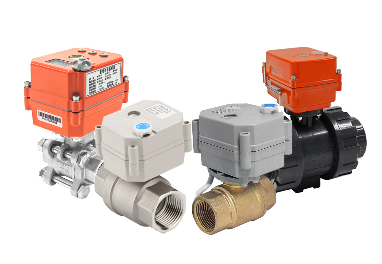
In the high-stakes environment of modern process automation, the transition from manual valves to automated systems is no longer a luxury – it is a baseline requirement for safety and efficiency. The electric rotary valve actuator serves as the critical bridge between digital control systems and physical fluid management. Unlike their pneumatic counterparts, which rely on the volatility of compressed air, electric actuators offer a level of repeatability and precision that is essential for complex chemical dosing, high-pressure steam regulation, and large-scale water treatment. However, to choose the right high torque electric rotary actuator, one must first dismantle the mystery of what happens beneath the protective housing.
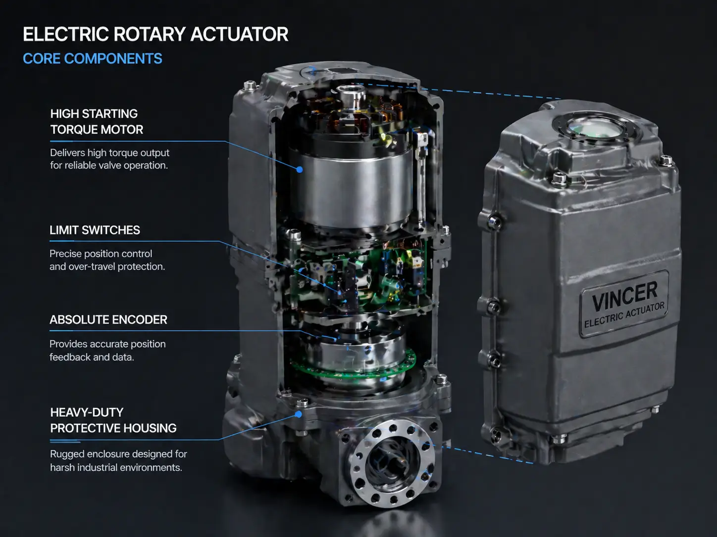
Key Components Inside the Actuator Housing
An industrial-grade electric actuator rotary is a marvel of miniaturized mechanical engineering. At its core is a specialized high-starting-torque motor, designed specifically to overcome the static friction of a seated valve. These motors are paired with sensitive “sensory” components: the limit switches and encoders. Mechanical limit switches define the hard stop positions, preventing the motor from over-traveling. In high-precision applications, an absolute encoder provides continuous feedback of the valve’s angular position. To protect these critical electronics from harsh environments, industrial standards dictate heavy-duty IP67/IP68 enclosures. Depending on the application, specific waterproof or explosion-proof housings are utilized to seal out corrosive elements and high-pressure washdowns.
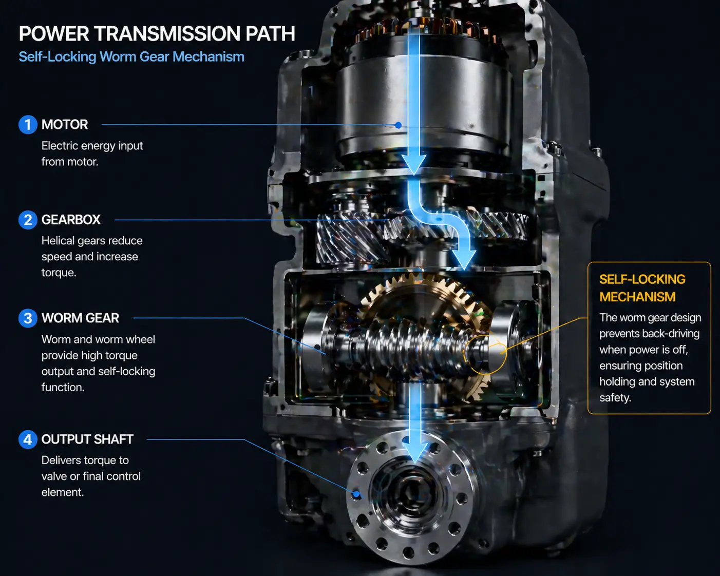
The Power Transmission Path and Self-Locking Mechanism
The translation of high-speed motor rotation into controlled, massive torque is achieved through a precision-engineered gearbox, typically utilizing a worm gear assembly. This rotary electric actuator transmission path is designed not just for power, but for stability. A critical engineering concept here is “Self-Locking.” In pipelines carrying high-velocity or high-viscosity fluids, the media exerts a constant “Back-driving” force on the valve disc. Without a self-locking mechanism, this pressure could force the valve out of its set position. The worm gear acts as a mechanical anchor; its unique geometry allows the motor to turn the valve, but physically blocks the valve from turning the motor, ensuring the valve stays locked even during a complete power loss.
Modulating vs On-Off Control in Rotary Applications
Defining the control logic is the most vital step in preventing “over-engineering” or equipment burnout. You must determine the frequency of operation before calculating torque, as the choice between On-Off and Modulating control dictates the entire electronic architecture and, critically, the motor’s duty cycle.
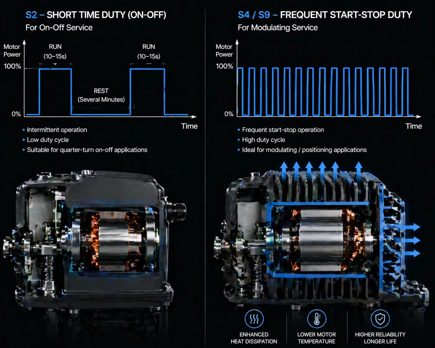
Duty Cycles: The S2 vs S4/S9 Motor Distinction
A frequent cause of actuator failure is applying the wrong motor type to a modulating task. On-Off Control logic is binary (100% open or closed) and is standard for isolation valves. These utilize S2 (Short-Time Duty) motors, engineered to run for brief periods (e.g., 10-15 minutes) before requiring a cooldown.
Conversely, Modulating Control allows precise flow regulation between 0° and 90°. Because the valve is constantly hunting for the perfect position, it requires an S4 or S9 (Continuous/Intermittent Periodic Duty) motor. These motors are built with specialized stator insulation and heat dissipation capabilities. Forcing an S2 motor into a high-frequency modulating application will rapidly melt the insulation and destroy the unit.
Flow Curve Mapping & Calibration: Utilizing standard 4-20mA or 0-10V DC signals does not inherently guarantee linear flow. To achieve true “Linearized” flow control, the actuator’s intelligent controller must feature Flow Curve Mapping and Calibration. Since standard rotary valves have non-linear flow characteristics, the controller is programmed to electronically compensate for the valve’s physical profile, ensuring a 50% command signal truly equates to 50% flow.
Actuator Sizing and Torque Calculation Strategy
Once the control logic is established, sizing is where engineering theory meets harsh reality. Selecting a high torque electric rotary actuator based only on the valve’s “nominal” torque is a recipe for failure. You must account for the physical state of the valve during its most difficult phase of movement.
Understanding Valve Breakaway Torque
The most critical parameter is the “Breakaway Torque” (BTO). This is the peak force required to unseat the valve after it has been sitting closed for an extended period. Over time, friction increases due to media deposits or seat deformation. If your actuator only matches the “Running Torque,” the motor will stall. Engineers must size for the BTO, which can be significantly higher than the running torque. Apply a mandatory safety factor – typically 20% to 30% for standard clean fluids, and up to 50% for slurry or highly viscous media – to prevent S2/S4/S9 motor stalling.
Comprehensive Application Analysis
At VINCER VALVE, our technical team evaluates your project across 8 critical dimensions: Media, Temperature, Pressure, Connection Standard, Control Method, Material Requirements, and Industry-specific standards.
For complex applications, our engineering team provides 2D/3D verified technical drawings and rapid preliminary proposals within 24 to 48 hours. By relying on over a decade of automation experience, we ensure your equipment sizing and safety factors are calculated certainties.
Electric vs Pneumatic Rotary Actuators Cost and Performance
While pneumatic systems may have a lower initial “sticker price,” evaluating the entire facility’s infrastructure is necessary to determine true Total Cost of Ownership (TCO).
Infrastructure and Real Energy Costs
A pneumatic actuator is supported by a complex, energy-intensive infrastructure. Consider the energy footprint: A typical 20hp air compressor running continuously to maintain system pressure (factoring in the industry-average 20% to 30% leakage rate in aging pipe networks) can cost upwards of $10,000 to $15,000 annually in electricity alone. In contrast, an electric actuator draws significant power only during its brief operating stroke, dropping to a negligible fractional-watt standby draw when holding position.
| Metric | Pneumatic System | Electric System |
|---|---|---|
| Energy & Standby Loss | High (Constant compressor load & leaks) | Negligible (Fractional-watt standby) |
| Infrastructure Need | Compressors, FRLs, Tubing | Standard Electrical Wiring |
| Positioning Precision | Approximate (Air compressibility) | Highly Precise (Digital Encoders) |
Balancing Initial Investment with Reliability
As an ISO9001 certified manufacturer with products meeting CE, RoHS, and SIL standards, VINCER VALVE delivers automation solutions that ensure industrial-grade durability. Rather than relying on empty promises, our product reliability is backed by the integration of high-end imported seals and precision CNC-machined internal components.
By leveraging our 7,200-square-meter in-house manufacturing facility, VINCER products offer extremely high cost-effectiveness. Under the premise of equally meeting usage requirements, we can greatly reduce customers’ procurement costs. We deliver a competitive cost advantage to “save your project costs, do more with less.” Combined with a delivery time of just 7 to 10 working days for standard products, this efficiency enables projects to rapidly transition to automation.
Essential Failsafe Features for Industrial Environment
In hazardous industrial zones, safety is defined by what happens when the primary power grid fails. A robust electric rotary actuator system must clearly distinguish between emergency safety mechanisms and maintenance overrides.
Emergency Shut Down (ESD): Spring Return & Battery Backup
For true emergency failsafe operation, actuators must be equipped with Mechanical Spring Return mechanisms or integrated Battery Backup Units (BBU). Upon total power loss, these systems automatically, without human intervention, drive the valve to a predetermined safe position (Fail-Open or Fail-Close). This is the ultimate line of defense against catastrophic spills.
Mechanical Override: The Declutchable Handwheel
Conversely, the Declutchable Manual Handwheel serves a completely different purpose: maintenance and mechanical override. It allows an operator to physically disengage the motor gearing and manually rotate the valve during plant commissioning or extended maintenance. Relying on a manual handwheel as an emergency “failsafe” is an engineering error; true safety requires automated backups.
Common Installation Mistakes and Troubleshooting Guide
The success of an automation project heavily depends on proper installation and commissioning.
- Concentricity and Alignment: If the actuator and the valve stem are misaligned, it induces “Side Loading.” This lateral force destroys the valve packing, leading to external leaks and potential fugitive emissions.
- Anti-Condensation Heater Neglect: In outdoor or highly humid environments, moisture is the primary cause of electronic failure. The internal “Space Heater” must be wired to a continuous power supply to prevent condensation from shorting the control board.
- Phase Rotation Errors & Protection: In traditional 3-phase units, incorrect wiring can cause the motor to drive in the wrong direction, leading to logic errors and potential mechanical jamming. However, modern intelligent actuators – such as those integrated into VINCER’s high-end solutions – feature Automatic Phase Sequence Protection and Correction. This ensures the motor always rotates correctly regardless of how the 3-phase power is wired.
Proactive Commissioning: By rigorously checking these installation fundamentals before fully powering up the system, engineers can safeguard the actuator’s electronic and mechanical integrity, effectively preventing costly unplanned downtime.
Conclusion: Precision and Reliability as a Strategy
Transitioning to high-torque electric rotary actuators is a strategic upgrade to your facility’s operational intelligence. By accurately defining your duty cycle (S2 vs S4/S9), sizing strictly for breakaway torque, and prioritizing automated failsafe mechanisms, engineers can drastically reduce Total Cost of Ownership.
By reallocating the $10,000 to $15,000 annually wasted on pneumatic compressor energy and air leaks, facilities can typically offset the initial investment difference of electric actuators within the first 12 months.
Stop guessing with your automation infrastructure. Partner with VINCER VALVE for transparent engineering data and multi-dimensional application support.