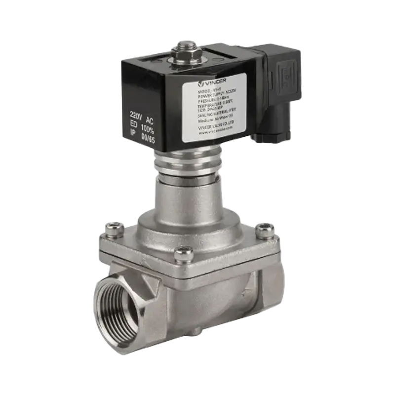
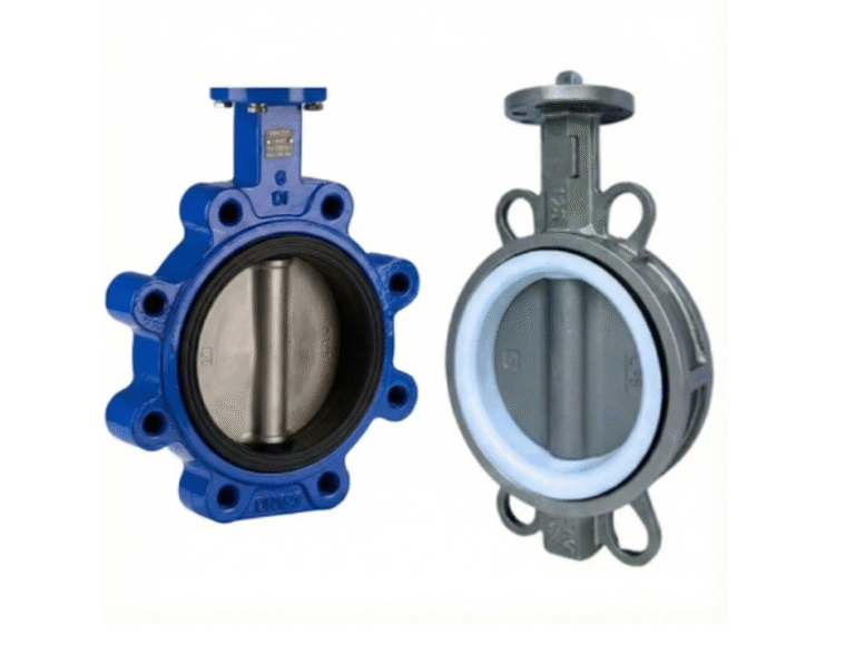
Cada vez que ves una válvula de mariposa en una línea de tratamiento de agua, una sala de instalaciones de climatización, una torre de refrigeración o un módulo químico, estás ante una de las máquinas más sencillas de las tuberías industriales: un disco montado en un eje que gira un cuarto de vuelta para abrirse y cerrarse. ¿Cómo funciona una válvula de mariposa? El mecanismo se explica en dos frases. Entender lo que puede y no puede hacer ocupa el resto de este artículo: analizaremos el giro de 90° en sí mismo, luego los tipos que se derivan de él, la decisión de automatizar y, por último, las condiciones en las que el principio de funcionamiento deja de funcionar.
¿Qué es una válvula de mariposa y cómo funciona?
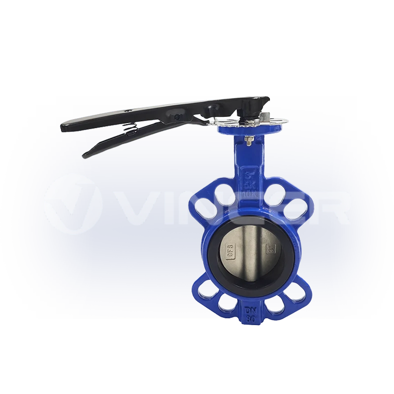
Una válvula de mariposa es una válvula de cuarto de vuelta que aísla o regula el caudal mediante la rotación de un disco alrededor de un vástago central. La “mariposa” es ese disco. Cuando la válvula está completamente abierta, el disco queda paralelo a la dirección del caudal; cuando está completamente cerrada, ha girado 90° hasta quedar perpendicular, bloqueando el paso (Wikipedia). Dado que una carrera completa es de solo 90°, la válvula se abre y se cierra más rápido que los modelos multigiro, como las válvulas de compuerta.
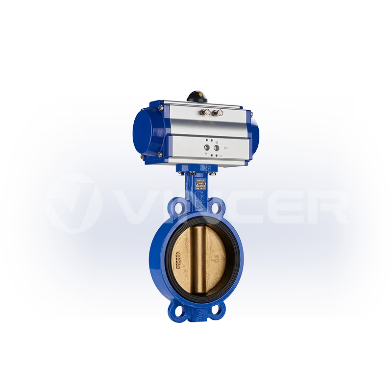
Este principio se basa en cuatro elementos:
- Cuerpo — la carcasa que se monta entre las bridas de las tuberías (tipo wafer, con orejetas o de doble brida).
- Disco — el elemento de cierre; gira para bloquear o dejar pasar el flujo.
- Tallo — transmite el movimiento giratorio desde el mango o el accionador al disco.
- Asiento — la superficie de sellado contra la que presiona el disco cuando está cerrado.
Su pariente más cercano es la válvula de bola: ambas son dispositivos de cuarto de vuelta y se abren y se cierran con un único giro de 90°. La diferencia que determina todas las decisiones de ingeniería posteriores es que, cuando está abierta, la bola de una válvula de bola se retira de la trayectoria del flujo, mientras que el disco de una válvula de mariposa se mantiene en el flujo. Ese único aspecto estructural hace que la válvula de mariposa no sea de paso total: siempre presenta cierta resistencia cuando está abierta, y las tuberías que la incorporan no pueden limpiarse mediante pigging. Es el precio que hay que pagar por ser ligera, compacta y considerablemente más barata que otras válvulas de gran diámetro, y es precisamente este hecho el que determina los principios físicos del sellado, los tipos de ramales y los límites de estrangulamiento que se tratan en el resto de este artículo.
Tipos de válvulas de mariposa: tres capas estructurales, un principio de funcionamiento
Existe exactamente un principio de funcionamiento, pero hay muchos tipos. Cada “tipo” de válvula de mariposa es el mismo mecanismo de 90° en el que se ha modificado una capa estructural: cómo encaja el disco en el asiento, cómo se monta la válvula en la tubería y de qué material está hecho el asiento. Lee las tres categorías que aparecen a continuación y podrás clasificar cualquier válvula de mariposa del mercado en su categoría correspondiente: cuál es el diseño predeterminado, cuál es el más versátil y cuál está pensada para casos extremos.
Estructura de la junta: concéntrica, de doble desplazamiento y de triple desplazamiento
La primera capa estructural es el acoplamiento de la junta: la forma en que el disco encaja con el asiento al cerrarse. ⭐ El diseño concéntrico (sin desplazamiento) es el más habitual en las válvulas de mariposa del mercado.: su vástago se sitúa en la línea central del disco, y cerrarla es como estampar un sello sobre el papel: el disco roza el asiento durante la última parte de la carrera. Ese contacto deslizante resulta perfectamente adecuado para asientos blandos en aplicaciones de agua y climatización, y permite que la válvula sea económica. El diseño de doble desplazamiento es la opción habitual para líneas de mayor tamaño y ciclos frecuentes. — El vástago está descentrado tanto respecto al centro del disco como al centro del orificio, por lo que el disco se separa del asiento en el momento en que se abre, en lugar de arrastrarse por él. Menos fricción, menos desgaste: por eso las redes municipales de agua utilizan diseños de doble descentrado. El diseño de triple desplazamiento es una variante poco común y de alta gama. — Un tercer desplazamiento cónico permite que el disco entre en contacto con el asiento sin deslizarse en absoluto, por lo que el asiento puede ser de metal duro, mecanizado para garantizar un cierre hermético a prueba de burbujas en aplicaciones de alta temperatura, alta presión y con hidrocarburos.
| Diseño | Cómo se acopla la junta | Fricción y desgaste | Funciones habituales | Posición en el mercado |
|---|---|---|---|---|
| Concéntrico (desplazamiento cero) | El disco se presiona directamente contra el asiento; se desliza por él | La mayor fricción de las tres | Agua, sistemas de climatización, tareas de baja presión | ⭐ El más habitual: la opción predeterminada para el servicio diario |
| Doble desplazamiento | La acción de la leva hace que el disco se separe del asiento al abrirse | La fricción se ha reducido considerablemente | Tuberías de gran diámetro, mayor presión, ciclos frecuentes: redes de agua | ⭐ Norma para el servicio de red |
| Triple desplazamiento | Contacto cónico metal con metal, sin deslizamiento | La fricción es insignificante; el desgaste se concentra en los momentos de cierre | Alta temperatura y presión, petróleo, gas y productos químicos | Raro — solo para productos de alta gama |
Una limitación de la que casi nadie habla: la calidad de un asiento metálico depende de cómo se haya cerrado por última vez. Si una válvula de triple desplazamiento se deja parcialmente abierta, se obstruye con residuos o no recibe la potencia suficiente debido a un actuador de tamaño insuficiente, el asiento metálico se desgasta, y ese desgaste no es reversible como ocurre con el de un elastómero (experiencia sobre el terreno, foro de ingeniería de válvulas Eng-Tips).
Conexiones en los extremos: tipo wafer, con terminal y de doble brida
La segunda capa estructural se refiere a cómo se monta la válvula en la tubería, y determina un aspecto práctico: si es posible trabajar en un lado de la válvula sin tener que vaciar toda la tubería. ⭐ La conexión tipo oblea (tipo wafer) es la más utilizada.: the valve sits sandwiched between two flanges with long through-bolts — compact, cheap, and impossible to use at the end of a line. The lug connection is the maintenance-friendly choice: threaded inserts on both faces let either side of the piping be disconnected independently, which is why it is the standard for end-of-line isolation. The double-flanged connection is the heavy-duty branch: its own flanges, for large diameters and high pressures.
The lug type carries one caution: in dead-end service it should be fitted with a blind flange, because its pressure rating drops — a lug valve rated at 150 psi between two flanges is rated at roughly half that when mounted with one flange (Wikipedia).
Seat Material: Soft Seats vs. Metal Seats
The third structural layer is the material that actually makes the seal, and it sets the temperature ceiling of the whole assembly. ⭐ Soft seats cover the vast majority of normal-duty applications: an elastomer (EPDM, NBR, PTFE) deforms slightly around the disc edge when the valve closes, producing a tight, often bubble-tight, seal at normal temperatures and pressures. Metal seats are the specialty branch: the disc closes against a precisely machined metal surface, which only pays off in high-temperature, high-pressure, or corrosive services where elastomers would fail.
| Material | Max Temp | Typical Service |
|---|---|---|
| EPDM | 120°C (248°F) | Drinking water — does not affect taste |
| NBR | 85°C (185°F) | Oil and water services |
| FKM | 180°C (356°F) | General chemical and heat resistance |
| PTFE / silicone | 200°C (392°F) | Aggressive media, steam-adjacent duties |
Exceed these numbers and the seat degrades — the working principle keeps turning the disc, but the valve stops sealing.
Put the three layers together and the market sorts itself: the default everyday valve is a concentric soft-seated wafer type; the network workhorse is double-offset soft-seated with a lug connection so it can be maintained section by section; and the premium extreme is a triple-offset metal-seated double-flanged valve. Choosing a butterfly valve is mostly choosing where on these three layers your duty sits.
Manual or Automated? The Butterfly Valve Decision Point
Who turns the stem? That is the first real decision a buyer faces, and it is no longer a neutral one. The same 90° mechanism can be rotated by hand (lever or gearbox), by compressed air (pneumatic actuator), or by an electric motor (electric actuator) — and the industry is quietly making automation the default.
Three observable forces are driving that shift. First, control architecture: plant networks now speak PLC/SCADA and 4–20 mA as their standard language, so a valve that cannot be commanded from the control room needs a separate manual operator — an exception to be justified, not a default. Second, labor: an actuated valve removes the walk, the wrench, and the re-check from every valve operation; plants trim operators, not valve automation. Third, new applications: data-center cooling and AI-era facilities treat actuated butterfly valves as a given, and the demand shows up in the market numbers — the global actuators market (all types: electric, hydraulic, pneumatic) was worth about USD 71 billion in 2025 and is projected to reach about USD 100 billion by 2030, roughly 7% per year (MarketsandMarkets, 2025).
The engineering track underneath all of this is already standardized. ISO 5211 defines the mounting interface that lets an actuator from any manufacturer bolt onto a butterfly valve from any other — which is exactly what an industry looks like when it is laying the rails for automation. A manual butterfly valve will not disappear; but in new projects, it is moving from the default to the exception. The question that follows is which actuator to choose — and that is the next section.
Pneumatic Butterfly Valve Working Principle: Air In, Disc Turns
A pneumatic butterfly valve is a butterfly valve with a pneumatic actuator bolted on — typically through that same ISO 5211 flange. Compressed air drives a rack-and-pinion mechanism inside the actuator; the actuator converts air pressure into torque on the valve stem; the stem rotates the disc the same 90° as a hand lever would. The working principle of the valve itself does not change — only the muscle does.
The parameters that matter are torque and air supply. As a reference band for quarter-turn duties: rack-and-pinion double-acting actuators typically deliver roughly 8–4,700 N·m, spring-return types about 5–2,800 N·m, and larger scotch-yoke units up to about 10,000 N·m, at supply pressures up to 8 bar and ambient temperatures of about −20°C to +80°C, with stroke response under a second (manufacturer series data). If the actuator cannot generate enough torque to push the disc to full closure against line pressure, the valve will “pass” — leak around the disc — no matter how good the seat is.
Single-Acting vs. Double-Acting: What Happens When the Air Goes Out
The first question engineers ask about pneumatic butterfly valves is what happens on air failure, and the answer is determined before the valve is ever ordered.
- Double-acting: air opens it, air closes it. If supply is lost, the valve stays where it is. Simple and cheap; no defined failure position.
- Single-acting (spring return): one direction is powered by air, the other by a spring. On air loss, the spring drives the valve to a defined fail-safe position — spring-to-close or spring-to-open.
Choosing between them is a process-safety decision, not a cost decision: chemical and water processes usually want spring-to-close (fail closed to contain the line), ventilation and dump services usually want spring-to-open. If your control system assumes “air loss = valve closes,” and the valve is double-acting, that assumption is fiction.
From On/Off to Modulation: Valve Positioners and Throttling
To make a pneumatic butterfly valve regulate rather than just open and close, it needs a valve positioner: a control loop that takes a 4–20 mA signal and moves the disc to a commanded angle, holding it there against process forces. This is where the butterfly’s flow characteristic enters the story, and it is not linear.
A butterfly valve has a roughly quick-opening characteristic: most of the flow change happens in the first part of the stroke. A small movement near the closed position produces a disproportionate flow swing, which is why a modulated butterfly valve is only comfortable working around the middle of its travel — engineering guidance puts the usable modulation band at roughly 30–60% open, with the valve often selected one nominal size smaller than the pipe so that the working point actually lands inside that band (Eng-Tips, valve engineering forum). What happens when you leave that band is covered later — but first, the other half of the automation story.
Specifying a pneumatic or electric butterfly valve?
Get the actuator matched to your duty — torque, fail-safe behavior and stroke time checked against your line size.
Ask for valve & actuator selectionMotorized Butterfly Valve Working Principle: Signal In, Torque Out
A motorized butterfly valve replaces the air muscle with an electric actuator: motor, gear train, and output drive mounted on the same ISO 5211 flange. The motor turns the gear train; the gear train multiplies torque and slows the output; the output turns the stem; the stem rotates the disc, to either of two positions (ON/OFF type) or to any commanded angle (modulating type with a 4–20 mA / 0–10 V signal).
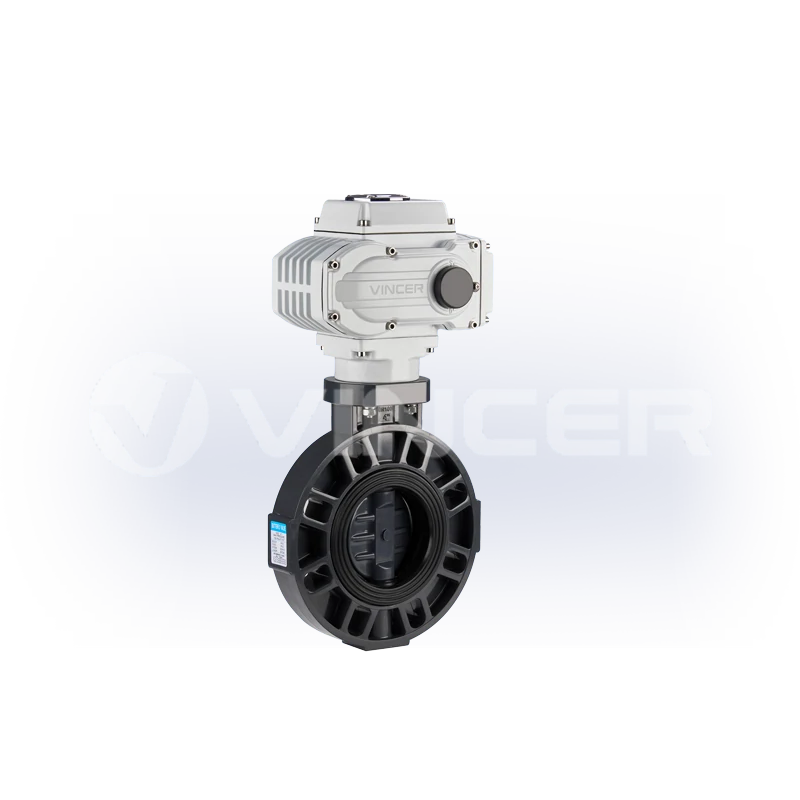
Torque and speed are the two numbers that decide whether the assembly does its job. As a reference band for quarter-turn electric actuators: output torques range from roughly 200 N·m for compact units (2.5–20 s stroke) up to about 4,000 N·m for large quarter-turn units (20–100 s stroke), with multi-turn versions beyond 10,000 N·m, in DC 12/24 V and AC 110/220/380 V variants (manufacturer series data). Electric actuation is the usual choice for precise modulating control, remote monitoring via PLC/SCADA, and sites without a reliable air supply.
How an Electric Actuator Turns the Disc — and Why Speed Matters
The power chain looks like this: signal → motor → gear reduction → output drive → stem → disc. The gear reduction is the part people misread. An electric actuator is slower than a pneumatic one because it trades speed for torque, and that slowness is often a feature, especially on large water lines.
Close a big butterfly valve too fast and you invite water hammer: the moving water column slams into the closing disc, and the pressure spike can damage valves, pipe supports, and pumps. A slow, controlled electric close over tens of seconds gives the water time to decelerate. When a pump station or water treatment spec calls for an electric butterfly valve, “how many seconds to close” is usually a deliberate engineering number, not an accident.
Electric vs. Pneumatic: Choosing the Driver for Your Duty
The two automation paths answer to different plant realities. The decision matrix that matters:
| Dimensión | Eléctrico | Neumático |
|---|---|---|
| Speed | 20–100 s stroke — slow, controlled | Under 1 s — fast |
| Power source | Mains or DC supply | Compressed air — needs a dry, filtered supply |
| Hazardous areas | Explosion-proof electric actuators available (ATEX-rated) | No electrical spark in the actuator itself, but ATEX certification must still be verified per unit |
| Modulation | 4–20 mA precise positioning as standard | Needs a positioner for modulation |
| Failure behaviour | Stays put, or spring-return variant on power loss | Stays put (double-acting) or spring to a defined position (single-acting) |
| Mantenimiento | Motor and gear wear, occasional | Seal wear and air quality discipline |
Two cautions. First, “no spark” is not the same as “certified”: a pneumatic actuator’s inherent suitability for explosive atmospheres does not itself grant an ATEX rating. The complete assembly has to be certified. Second, ISO 5211 is the common language that lets an electric or pneumatic actuator from one manufacturer mount on a butterfly valve from another — so the actuator choice stays independent of the valve choice, and the working principle of each half can be matched to the duty separately.
That is also where buying the driver and the valve from the same factory pays off: the torque matching is done before the quote, not after installation. VINCER publishes its electric and pneumatic actuator range openly: quarter-turn electric units from 200 N·m (2.5–20 s stroke) up to 4,000 N·m (20–100 s), multi-turn versions to 10,000 N·m, plus explosion-proof and waterproof variants. Pneumatic rack-and-pinion AT/ATS/AW series run from 8–4,678 N·m double-acting and 5.7–2,792 N·m spring-return up to 10,000 N·m, with under-one-second stroke response and no electrical spark in the actuator itself. The same factory builds the valves those actuators bolt onto, including pneumatic actuated butterfly valves in wafer, flanged, sanitary, plastic, hard-seated and PTFE-lined versions, and electric butterfly valves from compact wafer and lugged types up to auto-reset power-off designs, in sizes from 2″ to 24″. One factory, one torque table, one set of pressure-test records, and the working principle of each half matched on paper before anything ships.
When the Working Principle Breaks: Throttling Limits and the 30–60% Rule
Everything above described the butterfly valve doing what it does well. This section is about where the principle stops holding, because that is the information that keeps plants out of trouble, and it is almost never written down in “working principle” articles.
The danger zone is below 30% open. At small opening angles, the flow area narrows to a crescent. Fluid velocity through it rises sharply, the disc sits at a steep angle, and local pressure can drop below vapour pressure. The result is cavitation: vapor bubbles forming and collapsing at the disc edge, eroding the seat and even the downstream pipe wall. Field experience puts the rule simply: a butterfly valve throttled below about 30% opening risks cavitation damage, and the damage typically shows up first on the seat (Eng-Tips).
The trap is sizing the valve the same size as the pipe. If you need to throttle, and the valve matches the line diameter, the required flow may only be achieved at 15–25% opening — exactly the cavitation-and-chatter zone. The standard fix in control practice: select the butterfly valve one nominal size smaller than the pipe for modulating duty, so the working point returns to a healthy mid-stroke position.
And the corollary for plant engineers: when the duty keeps a butterfly below 30% continuously, the answer is not a better butterfly — it is a different valve. The boundary matrix below is the horizontal version of everything above — scenario, valve, and the line not to cross:
| Scenario | Valve Choice | Límite |
|---|---|---|
| On/off isolation, large water or gas lines | Concentric soft-seated butterfly | Perfect — do not throttle it |
| Frequent flow adjustment (raw or process water) | Butterfly one size smaller than pipe, kept in 30–60% band — otherwise a control valve | Continuous <30% opening = switch signal |
| High-temperature, high-pressure tight shut-off (oil, gas, chemical) | Triple-offset metal-seated butterfly | Full closure mandatory; partial closure wears the metal seat |
| End-of-line isolation with one side maintainable | Lug butterfly with blind flange | Pressure rating drops in dead-end duty |
| Slurries, solids-laden media | Knife gate valve | Butterfly seats wear quickly on abrasives |
These boundaries are why the standards exist: butterfly valves for industrial duty are designed and tested to norms such as EN 593 (industrial butterfly valves) and API 609 (butterfly valve standard), and matching valve, seat, and actuator to the duty is precisely what a proper selection process, not a price sheet, is for.
What the Working Principle Means for the People Buying Valves
That last boundary, “when the duty keeps a butterfly below 30%, the answer is a different valve,” is a decision someone has to own. In the projects where these valves are specified, that ownership is exactly where the money leaks, because the people who choose the valve are usually not the people who suffer the failure.
Look at what actually happens in the field. Plant teams throttling raw or process water with a butterfly valve watch the seat die within a short operating window and the valve lose both control and isolation duty, the classic “seat damage in flow-adjustment service” story from the engineering forums. The root causes are always the same three, and all three are decisions made before the valve is ever bolted in. The valve was sized to match the pipe instead of the duty. The working opening was left in the 15–30% zone instead of the 30–60% band. And the seat material was chosen by price rather than by media temperature. None of these show up on a drawing. They show up as downtime, and downtime is the most expensive line item on any valve’s lifetime bill.
For the people buying these valves, the translation is direct. In project procurement, put three clauses in the specification: the valve-to-pipe size ratio for any modulating service, the required working opening band, and the seat material temperature ceiling for the actual media — and the seat-damage failures largely stop being your problem. For equipment OEMs, document the failure behaviour (fail-open or fail-closed on air/power loss) in the selection documents, because a control philosophy that assumes the wrong failure position is a safety incident waiting for a power cut. And when comparing suppliers, price the selection as much as the valve: an assembly that cannot close fully because the actuator is under-torqued is a leak, a rework, and a claim — not a discount.
Three clauses that belong in the specification
Now for where the money actually sits in this product family — because it matters for every buyer, and especially for distributors and equipment builders deciding what to stock. A bare butterfly valve is close to a commodity: its price is on every directory, and its margin gets squeezed toward zero. The actuated assembly is a different product. The moment you add an actuator, the value moves into things a catalogue price cannot express: torque matching against the valve’s actual seat load, the ISO 5211 interface decision, the fail-safe logic, the control integration. That is engineering work, and engineering work cannot be commoditized. The market data in the decision-point section said the same thing from the demand side — automation is where the growth is — and the profit follows the same direction. If you are building a product line or a stock list around butterfly valves, the defensible position is the actuated assembly: valve plus actuator, matched and tested as one unit. The bare valve is the entry ticket; the actuator is where the margin lives.
That is also why the supplier question is really a capability question. The working principle itself is public knowledge — every manufacturer’s website explains the 90° turn. What separates suppliers is what happens before the quote: whether the valve, seat, and actuator are matched to media, temperature, pressure, connection standard, control method, material, and industry characteristics — the full selection screen, not just the price column. On the delivery side, the published figures matter. Stock items leave in about five working days, custom builds in about twenty, per the manufacturer’s own published lead times (pneumatic valve page FAQ). And when a valve “won’t close,” “won’t install,” or “leaks,” the after-sale response — free spare parts, remote technical guidance, engineers who analyse before replacing — is the difference between a week of downtime and a morning.
When the working principle has to be matched to a real duty — media, temperature, pressure, connection standard, control method, body material and industry characteristics — that matching is selection engineering, and it is where the supplier’s actual capability shows. Send your duty to VINCER’s selection engineers and get a proposal within 48 hours, starting from their butterfly valve range.
Get your butterfly valve selection checked against the 30–60% rule
Send your line size, media, temperature and pressure — the engineering team replies with a selection proposal.
Request a selection proposalReferencias
- Wikipedia. “Butterfly valve” — quarter-turn definition, disc-in-flow, wafer/lug dead-end pressure derating. https://en.wikipedia.org/wiki/Butterfly_valve
- Tameson. “What is a Butterfly Valve?” — seat material temperature limits, ISO 5211/NAMUR mounting, selection criteria. https://tameson.com/pages/butterfly-valve
- Eng-Tips (Valve Engineering forum). “Butterfly Valves used for flow adjustment in raw water service experiencing valve seat damage” — 30% cavitation line, 30–60% throttling band, oversized-valve rule. https://www.eng-tips.com/threads/butterfly-valves-used-for-flow-adjustment-in-raw-water-service-experiencing-valve-seat-damage.459593/
- MarketsandMarkets. “Actuators Market — Global Forecast to 2030” — USD 71.22B (2025) → USD 100.41B (2030), CAGR 7.1%, all actuator types (electric/hydraulic/pneumatic). https://www.marketsandmarkets.com/Market-Reports/global-actuators-market-59465451.html
- VINCER Valve. Butterfly valve series — wafer/lug/double-flanged, 2″–24″, sealing options. https://www.vincervalve.com/vincer-butterfly-valve-series/
- VINCER Valve. Contact for a quote. https://www.vincervalve.com/contact-for-a-quote/
- VINCER Valve. Página de inicio. https://www.vincervalve.com/
- VINCER Valve. Electric and pneumatic actuator range — VQ/VM quarter-turn, multi-turn, explosion-proof, waterproof electric; AT/ATS/AW pneumatic; torque 200 N·m–10,000 N·m. https://www.vincervalve.com/vincer-automatic-valve-actutors/
- VINCER Valve. Pneumatic actuated valves — pneumatic butterfly valve family (wafer, flanged, sanitary, plastic, hard-seated, PTFE-lined); response <1 s; hazardous-environment suitability. https://www.vincervalve.com/pneumatic-actuated-valve/