إذا كنت قد حددت الصمامات المطلوبة لنظام الأنابيب، فمن شبه المؤكد أنك واجهت السؤال التالي: هل تختار الصمام الكروي أم الصمام الفحص؟ لا يشبه هذان النوعان بعضهما البعض على الإطلاق، ويخدمان أغراضًا مختلفة جذريًّا، ومع ذلك يتم مقارنتهما باستمرار جنبًا إلى جنب — في جداول بيانات المشتريات، وعلى رسومات P&ID المُعلَّمة، وأثناء مراجعات التصميم.
الإجابة المختصرة: الصمام الكروي هو جهاز تحكم يدوي أو آلي للتشغيل والإيقاف، في حين أن الصمام الفحص هو صمام أحادي الاتجاه يعمل تلقائيًّا ويمنع التدفق العكسي. لكن الاختلافات العملية أعمق من ذلك. فهي تمتد لتشمل قيم الضغط المسموح بها، وتسلسل التركيب، وأنماط الأعطال، وتكلفة دورة الحياة. يوضح هذا المقال تلك الاختلافات، ويشرح أيضًا — وهو أمر لا يقل أهمية — كيف يعمل هذان الصمامان معًا في نظام مصمم جيدًا.
ما هو الصمام الكروي؟
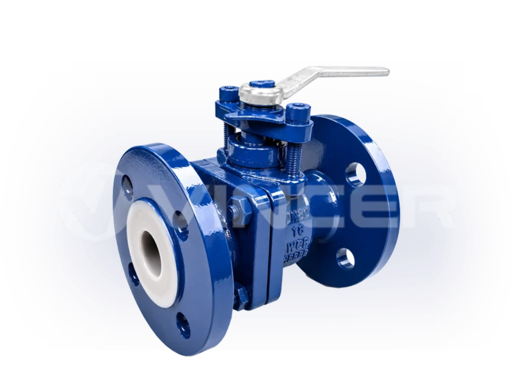
الصمام الكروي هو صمام ربع دورة يتحكم في التدفق باستخدام كرة مجوفة دوارة بها فتحة في مركزها. عند تدوير المقبض 90 درجة، تتوافق الفتحة مع اتجاه خط الأنابيب فيمر السائل عبرها. وعند إرجاعه إلى الوضع الأول، يسد سطح الكرة الصلب الممر تمامًا.
يستحق الصمام الكروي مكانته في الأنابيب الصناعية بفضل جودة إغلاقه. فالصمام الكروي ذو الممر الكامل — حيث يتطابق قطر التجويف مع القطر الداخلي للأنبوب — لا يتسبب عمليًّا في أي انخفاض في الضغط عند فتحه. وعند إغلاقه، يمكن للصمام الكروي ذي المقعد المعدني أن يحقق إحكامًا من الفئة السادسة (Class VI) — أي عدم وجود أي تسرب مرئي. وقليلة هي أنواع الصمامات الأخرى التي تجمع بين المقاومة المنخفضة عند الفتح والعزل المطلق عند الإغلاق بهذه الدرجة من الكفاءة.
تُستخدم الصمامات الكروية في جميع الأماكن التي يحتاج فيها المشغلون إلى تحكم موثوق به في التشغيل والإيقاف: عزل المضخات، وإغلاق مخرج الخزانات، ودوائر الإغلاق في حالات الطوارئ (ESD)، وأي تطبيق يتطلب إغلاق الخط بإحكام لأغراض الصيانة. ويمكن تشغيلها يدويًّا باستخدام ذراع يدوي أو علبة تروس، أو آليًّا باستخدام مشغلات كهربائية أو هوائية للتشغيل عن بُعد وبطريقة آمنة من الأعطال.
ما هو الصمام الفحصي؟
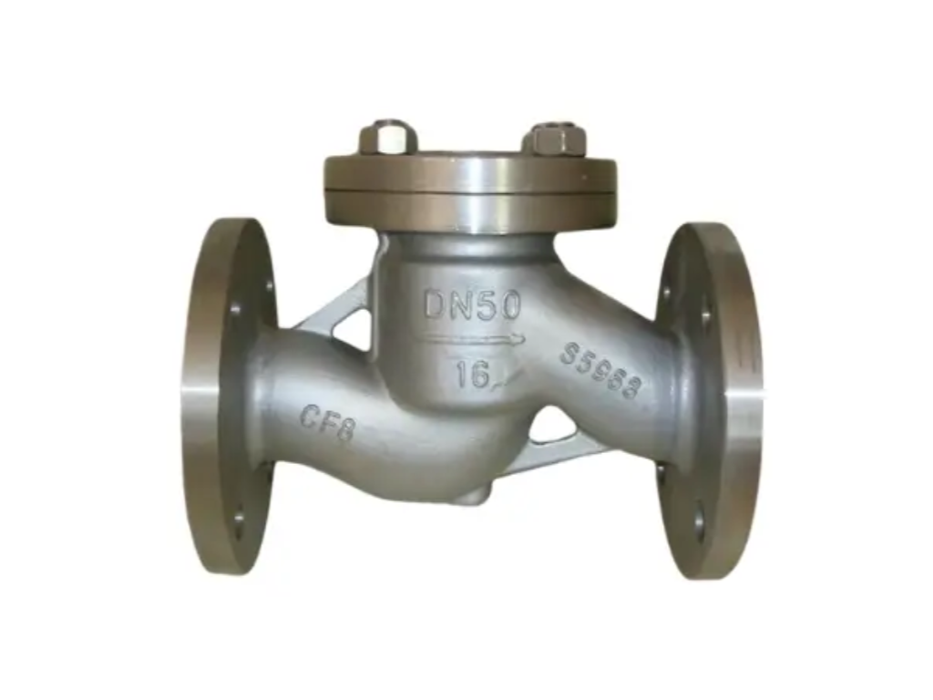
صمام الفحص — الذي يُعرف أيضًا باسم صمام عدم الرجوع أو الصمام أحادي الاتجاه — هو جهاز يعمل تلقائيًّا ويسمح للسائل بالتدفق في اتجاه واحد فقط. وعندما يتجاوز الضغط الأمامي ضغط الانفتاح الخاص بالصمام، ترتفع الآلية الداخلية (سواء كانت قرصًا أو كرةً أو صمامًا كرويًّا أو مكبسًا) عن مقعدها وتسمح بمرور السائل. وفي اللحظة التي يتوقف فيها التدفق أو يحاول العودة في الاتجاه المعاكس، تنغلق الآلية على المقعد وتمنع التدفق العكسي. ويحدث كل هذا تلقائيًا، دون أي أمر خارجي.
وتعد هذه الاستقلالية أكبر نقطة قوة في صمام الفحص ونقطة ضعفه الخفية في الوقت نفسه. فهو لا يحتاج إلى مصدر طاقة، ولا إلى إشارة تحكم، ولا إلى مشغل. ويمكن تركيبه في خندق الأنابيب، أو على سطح المبنى، أو تحت الماء، وسيستمر في أداء مهمته. لكنه في المقابل لا يمكن إصدار أمر له بالفتح أو الإغلاق. وعندما يتعطل، غالبًا ما يحدث ذلك بصمت، دون أي مؤشر خارجي على فقدان الحماية من التدفق العكسي.
هناك أربعة أنواع شائعة من الصمامات المانعة للرجوع تغطي معظم التطبيقات الصناعية:
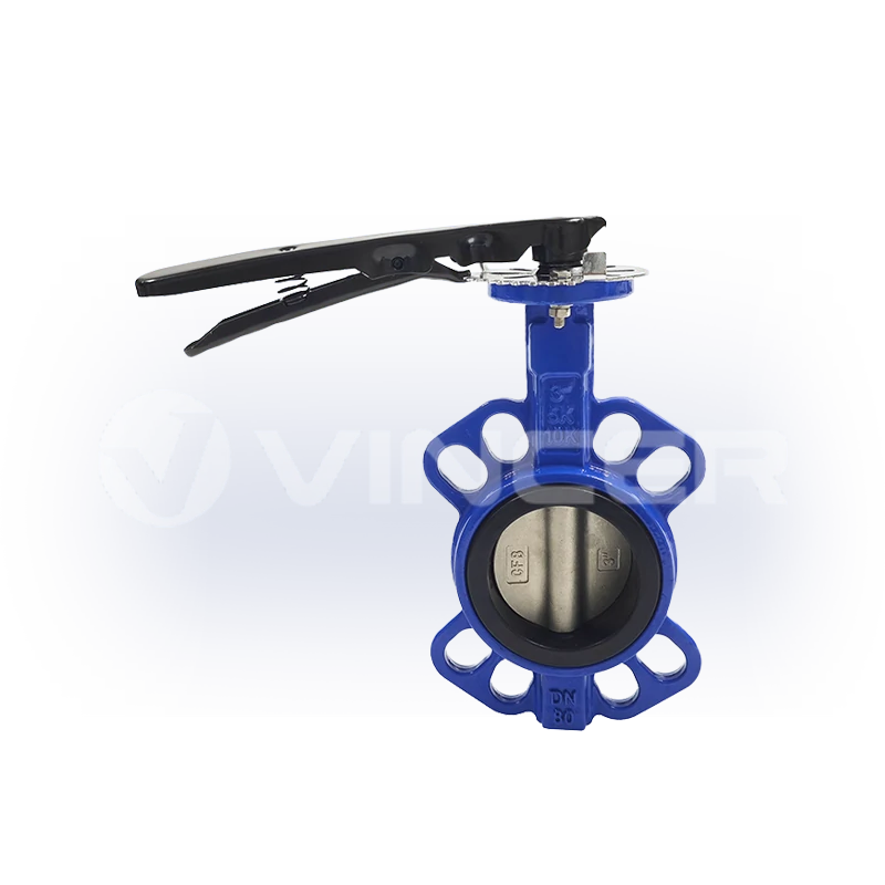
- فحص التأرجح: يتأرجح القرص المفصلي ليفتح مع التدفق الأمامي، ويغلق بفعل الجاذبية والتدفق العكسي. وهو الأنسب للمسارات الأفقية والأقطار الكبيرة التي يُعد فيها انخفاض الضغط عاملاً مهمًا.
- فحص الكرة: ترتفع كرة مزودة بثقل أو بنظام زنبركي عن المقعد. ويوفر حركة تدحرج الكرة تأثيرًا ذاتي التنظيف، مما يجعلها مناسبة للسوائل اللزجة أو التي تحتوي على جسيمات.
- الربيع / نمط المربعات الصغيرة: يضمن القرص أو الصمام الكروي المزود بنابض إغلاقًا محكمًا بغض النظر عن اتجاهه. ويتميز بإغلاق أسرع مقارنةً بالأنواع المتأرجحة، مما يقلل من ظاهرة «الضربة المائية»، على أن يكون ذلك على حساب ضغط فتح أعلى قليلاً.
- فحص المكبس: يتحرك مكبس مزود بثقل صعودًا وهبوطًا داخل أسطوانة موجهة. ويوفر تأثيرًا تخميديًّا شبيهًا بمخمد الصدمات، مما يعمل على تسوية التدفق النابض، ويُستخدم عادةً في خطوط تصريف الضاغط.
الصمام الكروي مقابل الصمام الفحصي: 5 اختلافات أساسية يجب على كل مهندس معرفتها
قبل مقارنة الأبعاد الفردية، يجدر توضيح الفرق الأساسي بوضوح: الصمام الكروي هو جهاز يمكنك الأمر. ولا يقوم بأي شيء حتى تأمره أنت أو جهاز التحكم المنطقي القابل للبرمجة (PLC) بالتصرف. والصمام الفحص هو حارس. فهو يعمل تلقائيًّا كحارس، ولن تدرك أنه تعطل إلا بعد أن تكون المعدات الواقعة في المرحلة التالية قد تعرضت للتلف بالفعل. وفهم هذا الفصل يفسر كل ما سيأتي بعده.
الوظيفة الأساسية: التحكم النشط في التدفق مقابل منع التدفق العكسي التلقائي
يتمثل الاختلاف الأساسي بين هذين الصمامين في الغرض من وجودهما.
يتحكم الصمام الكروي في التدفق حسب الحاجة. وعندما يحتاج النظام إلى تشغيل أو إيقاف أو عزل جزء من الأنبوب، ينفذ الصمام الكروي هذا الأمر — إما يدويًّا عن طريق ذراع يدوي، أو تلقائيًّا من خلال مشغل كهربائي أو هوائي يتلقى إشارة تحكم. ويقرر المشغل متى يتم فتحه وإغلاقه.
يمنع الصمام الفحص حدوث نوع معين من الأعطال: التدفق العكسي. فإذا تعطلت المضخة، يغلق الصمام الفحص الموجود على خط تصريفها قبل أن يتمكن عمود الماء من الاندفاع عكسيًّا نحو المكره. وإذا فقد خزان الهواء المضغوط ضغطه، يمنع الصمام الفحص الأنابيب الواقعة في اتجاه مجرى التدفق من الارتجاع. ولا يحتاج أحد إلى ملاحظة الحدث لكي تعمل آلية الحماية؛ فذلك يحدث بناءً على قوانين الفيزياء البحتة.
لماذا يُعد هذا الأمر مهمًا؟: يُعد استخدام الصمام الكروي كبديل للصمام الفحص أمرًا خطيرًا. فقول “سأغلقه فور حدوث ارتجاع” يفترض أنك ستلاحظ الأمر في الوقت المناسب. لكن حالات الارتجاع تحدث في غضون ثوانٍ. وبحلول الوقت الذي يصل فيه المشغل إلى الصمام، قد تكون المضخة قد تعرضت للتلف بالفعل.
الصمام الكروي هو جهاز تتحكم فيه. أما الصمام الفحص فهو بمثابة حارس — فهو يقوم بمهمة الحراسة تلقائيًّا، ولن تدرك أنه تعطل إلا بعد أن تكون المعدات الواقعة في اتجاه التدفق قد تعرضت للتلف بالفعل.
طريقة التشغيل: يدوية أو تعمل بمحرك مقابل تشغيل ذاتي بالكامل
تتطلب الصمامات الكروية مصدر طاقة لتغيير حالتها. وفي أبسط الحالات، تكون هذه الطاقة عبارة عن فني صيانة يقوم بتحريك ذراع يدوي. أما في المنشآت الآلية، فتكون هذه الطاقة عبارة عن تيار مستمر بجهد 24 فولت، أو تيار متردد بجهد 110 فولت أو 220 فولت أو 380 فولت، يُزود مشغلًا كهربائيًّا بالطاقة، أو هواء مضغوط بضغط يتراوح بين 4 و7 بار يُشغّل مجموعة تروس مسننة تعمل بالهواء المضغوط.
لا توجد مثل هذه المتطلبات بالنسبة للصمامات أحادية الاتجاه. فمصدر الطاقة هو ضغط السائل نفسه. حيث يدفع التدفق الأمامي الآلية لفتحها؛ وعند توقف التدفق، تعمل الجاذبية أو قوة الزنبرك أو الضغط العكسي على إغلاقها.
التطبيق الهندسي واضح ومباشر، لكنه غالبًا ما يُغفل أثناء تصميم التخطيط: يجب تركيب الصمام الكروي في مكان يمكن لأي شخص أو أي شيء الوصول إليه. أما الصمام الفحص فيمكن تركيبه في أي مكان يمر فيه الأنبوب — داخل قبو مدفون، أو في أعلى أنبوب صاعد رأسي، أو خلف جدار. وفي محطات الضخ حيث المساحة الأرضية ضيقة والوصول محدود، غالبًا ما يحدد هذا الفرق وحده نوع الصمام الذي يجب تركيبه في كل مكان.
اتجاه التدفق: ثنائي الاتجاه مقابل أحادي الاتجاه بشكل صارم
يسمح الصمام الكروي القياسي، عند فتحه، بالتدفق في كلا الاتجاهين. (توجد تصميمات محددة ذات مقاعد معدنية مخصصة للضغط العالي مع اتجاه إغلاق مفضل، لكن هذه حالات استثنائية وليست هي القاعدة.) هذه القدرة على التدفق في اتجاهين تجعل الصمامات الكروية متعددة الاستخدامات في الخطوط التي قد ينعكس فيها اتجاه التدفق خلال أوضاع التشغيل المختلفة.
صمام الفحص مصمم ليكون أحادي الاتجاه، ويؤدي الخطأ في هذا الأمر إلى عواقب حقيقية. ويحمل كل جسم صمام فحص سهمًا يشير إلى اتجاه التدفق. وإذا كان السهم يشير إلى الاتجاه الخاطئ، فإن التدفق العكسي سيدفع الآلية فتح بدلاً من أن يكون مغلقاً، مما يجعل الصمام عديم الفائدة تماماً. العطل له حالتان: إما أن الصمام لا يستطيع الفتح (لا يوجد تدفق عبر النظام، وهو أمر واضح على الفور) أو أنه لا يستطيع الإغلاق (تتلاشى الحماية من التدفق العكسي، وهو أمر خفي وخطير).
كما أن صمامات الفحص المتأرجحة تعتمد على الاتجاه بشكل يتجاوز مجرد اتجاه التدفق: فهي تعتمد على الجاذبية للمساعدة في إغلاقها، لذا فإن التركيب الرأسي يتطلب عادةً تدفقًا صاعدًا. أما صمامات الفحص المزودة بنابض فهي أكثر مرونة، حيث تعمل في أي اتجاه، مما يجعلها الخيار الأكثر أمانًا عندما يكون مسار الأنابيب معقدًا.
يؤدي تركيب صمام منع التدفق في الاتجاه المعاكس إلى إحدى نتيجتين — انعدام التدفق (وهو أمر واضح على الفور) أو انعدام الحماية من التدفق العكسي (وهو أمر خفي، لكنه كارثي). ولا يوجد حل وسط.
تحمل الضغط والحرارة
تتميز الصمامات الكروية ذات المقاعد المعدنية بنطاق تشغيل واسع بشكل ملحوظ. واعتمادًا على مادة هيكل الصمام وتصميم المقعد، يمكنها التعامل مع الفئات من 150 إلى 2500 (من PN 20 إلى PN 420)، مع نطاقات درجات حرارة تمتد من الاستخدامات المبردة (-196 درجة مئوية) إلى السبائك المقاومة للحرارة العالية التي تتجاوز 800 درجة مئوية. يبلغ الحد الأقصى لدرجة الحرارة للصمام الكروي القياسي المصنوع من الفولاذ الكربوني المصبوب WCB والمزود بمقاعد من مادة PTFE حوالي 200 درجة مئوية؛ ويمكن استبدالها بمقاعد من مادة RPTFE لدرجة حرارة تصل إلى 230 درجة مئوية، أو من مادة PEEK لدرجة حرارة تصل إلى 260 درجة مئوية، أو بمقعد معدني بالكامل للاستخدامات المتعلقة بالهيدروكربونات عالية الحرارة.
تعمل الصمامات الحابسة في نطاق أضيق. تصل معظم الصمامات الصناعية ذات الاتجاه الواحد إلى الفئة 600 كحد أقصى، وعادةً ما يكون الحد الأقصى لدرجة حرارتها مقيدًا ليس بمواد هيكل الصمام بل بالمكونات الديناميكية الداخلية. فالنابض الموجود داخل صمام ذي اتجاه واحد مزود بنابض سيفقد صلابته عند التعرض لدرجة حرارة عالية مستمرة قبل وقت طويل من وصول هيكل الصمام نفسه إلى الحد الأقصى لمقاومة المواد. كما أن مسمار مفصلة الصمام المتأرجح، الذي يعمل في سائل ساخن ومسبب للتآكل دون تزييت، يمثل نقطة فشل شائعة لا توجد في الصمام الكروي ذي الإغلاق الثابت.
| معلمات التشغيل | صمام كروي (النطاق النموذجي) | صمام منع الرجوع (النطاق النموذجي) |
|---|---|---|
| فئة الضغط | الفئة 150–2500 | الفئة 125–600 |
| درجة الحرارة (مقعد من مادة PTFE) | من -29 درجة مئوية إلى 200 درجة مئوية | غير متوفر (مقعد معدني/معدني نموذجي) |
| درجة الحرارة (المقعد المعدني) | من -196 درجة مئوية إلى 800 درجة مئوية+ | من -29 درجة مئوية إلى 540 درجة مئوية |
| العامل المحدد الرئيسي | مادة المقعد | مادة الزنبرك الداخلي أو المفصلة |
مقارنة التكاليف: الشراء الأولي مقابل الجدوى الاقتصادية على مدار دورة الحياة
لا تعكس بطاقات الأسعار سوى جزء من الصورة، لكنها تحدد التوقعات. بالنسبة لصمام ذي حواف من الفئة DN50 مصنوع من الفولاذ الكربوني المصبوب WCB، يتراوح سعر الصمام الكروي اليدوي عادةً بين $50 و150، في حين يتراوح سعر الصمام الفحص المتأرجح من نفس الحجم والمادة بين $40 و120. أما في حالة الفولاذ المقاوم للصدأ 316، فتتغير هذه الأرقام لتتراوح تقريبًا بين $150 و400 للصمام الكروي، وبين $100 و300 للصمام الفحص. وإذا أُضيف مشغل كهربائي إلى الصمام الكروي، فإن سعر الحزمة يرتفع بمقدار $200–800 اعتمادًا على متطلبات عزم الدوران وميزات التحكم.
لكن الحديث عن التكلفة لا ينبغي أن يتوقف عند أمر الشراء. فالصمام الفحص الذي تبلغ تكلفة شرائه $80 يحمي مضخة تبلغ تكلفة إصلاحها أو استبدالها ما بين $3,000 و15,000. أما الصمام الكروي المزود بنظام إغلاق مانع للتسرب تمامًا، والذي يتيح إجراء الصيانة دون الحاجة إلى إيقاف تشغيل النظام بأكمله، فيعوض تكلفته بمجرد أن يمنع توقف الإنتاج للمرة الأولى.
السؤال الصحيح ليس “أي صمام أرخص؟” بل “ما هي تكلفة العطل الذي يمنعه هذا الصمام؟” وعادةً ما تتفوق الإجابة على فارق السعر بكثير.
متى يستخدم كل صمام: جدول مرجعي سريع لاتخاذ القرار
تصف الأقسام السابقة ما يلي: كيف تختلف هذه الصمامات عن بعضها. ويُقدِّم الجدول أدناه دليلاً عملياً للاختيار يستند إلى هذه الاختلافات: ففي حالة وجود حاجة محددة، يوضح الجدول الصمام الذي يلبي هذه الحاجة، والسبب وراء ذلك.
| إذا احتجت إلى… | اختر | لماذا |
|---|---|---|
| منع التدفق العكسي تلقائيًا دون تدخل بشري أو تدخل من نظام التحكم | صمام فحص | تعمل تلقائيًا — تُغلق عند انعكاس اتجاه التدفق في غضون أجزاء من الألف من الثانية |
| إيقاف التدفق يدويًّا أو عن بُعد لعزل المعدات | صمام كروي | إغلاق محكم ومقاوم للتسرب؛ يتوفر إحكام من الفئة السادسة |
| حماية المضخة أو الضاغط أو المعدات الموجودة في المرحلة الأولية من التلف الناتج عن التدفق العكسي | صمام فحص | Installed immediately at pump discharge; first line of defense |
| Isolate a section of pipe for maintenance without draining the system | صمام كروي | Reliable zero-leakage isolation in both directions |
| Handle pressure classes above Class 600 | صمام كروي | Standard designs available to Class 2500 |
| Install in a remote, hard-to-access location where no operator will ever visit | صمام فحص | Zero external energy or human access required |
| Achieve emergency shutdown (ESD) with a fail-safe close on loss of power or air | صمام كروي | Spring-return actuators provide fail-close or fail-open on signal loss |
| Ensure one-way flow only — no exceptions | صمام فحص | Designed exclusively for unidirectional flow; flow arrow is mandatory |
Most industrial systems need both: the check valve protecting equipment automatically, the ball valve giving operators controlled isolation points. The next section covers exactly how they are arranged together in practice.
Most industrial systems need both — the check valve protecting equipment automatically, the ball valve giving operators controlled isolation points.
How Ball Valves and Check Valves Work Together: Pump Discharge and Beyond
In real piping design, ball valves and check valves are not alternatives. They are a fixed pairing, and the sequence in which they are installed is not negotiable. The standard layout, repeated across thousands of pump stations, compressor skids, and process lines worldwide, is:
Pump → Check Valve → Ball Valve → Downstream System
Here is why this order exists, and where else the same pairing logic applies.
The Standard Pump Discharge Configuration: Check Valve Before Ball Valve
In a pump discharge line, the check valve sits closest to the pump nozzle. Its job is to slam shut the instant the pump stops, preventing the fluid column in the downstream piping from reversing direction and spinning the impeller backward or hammering the pump casing. Water hammer from a swing check that closes too slowly can generate pressure spikes 3 to 5 times the normal operating pressure — enough to crack flanges or rupture gaskets. Spring-loaded check valves reduce this risk with faster, controlled closure.
The ball valve follows after the check valve, not before. This order matters. Every check valve eventually wears out or jams. When it does, you need to isolate it for repair. With the ball valve downstream, you close it, and the check valve is safely trapped between the pump (valved off on the suction side) and the closed ball valve. No need to drain kilometers of downstream piping. Reverse the positions — ball valve between pump and check valve — and the check valve sits downstream of your only isolation point, unreachable without draining the entire discharge header.
A practical detail that often gets skipped in spec sheets: leave 5 to 10 pipe diameters of straight run between the pump discharge flange and the check valve inlet. The pump impeller generates turbulent, swirling flow. If that turbulence hits a check valve disc before it settles into a uniform velocity profile, the disc flutters, cycling between partially open and closed and wearing the hinge pin and seat at an accelerated rate. A short straight spool piece costs almost nothing and can extend the check valve’s service life by years.
For engineers specifying both valve types in a pump discharge setup, sourcing ball valves and check valves from a single manufacturer simplifies procurement in two concrete ways: flange drilling patterns and pressure ratings are guaranteed to match without cross-referencing two separate catalogues, and delivery timelines for both valves can be coordinated under a single purchase order. Vincer, for example, produces full-port and V-port ball valves alongside swing, ball, spring, and piston check valves — with material options spanning 50+ grades including SS316, WCB, and PVDF — so the valve pair can be matched to the same media and service conditions without compromise.
Other Common System Configurations
The pump discharge layout is the most common pairing, but the same logic — check valve for automatic protection, ball valve for controlled isolation — shows up across other process systems:
- Compressed air systems: A check valve at the receiver tank outlet prevents stored air from flowing backward into the compressor head during unload cycles. A ball valve downstream lets maintenance isolate the distribution header without venting the entire tank.
- Chemical injection lines: A check valve (often a double-check assembly for contamination prevention) stops the main process stream from back-flowing into the injection quill. A ball valve upstream of the injection point provides a positive shutoff for injector replacement.
- Boiler feedwater: The check valve on the feedwater line prevents steam or hot water from reversing into the feed pump and deaerator during pressure transients. The ball valve downstream isolates the boiler side for inspection without shutting down the feed system.
Maintenance Schedules and Failure Modes: What Your Valve Manual Leaves Out
Most valve comparison articles end at the selection guide. But once the valves are installed, what actually happens over years of service? The two types age very differently, and the maintenance strategy needs to account for that asymmetry.
Ball Valve Maintenance: A Quarterly Checklist
Ball valves have one well-known weakness: if left in one position for months or years, the stem can seize. The packing around the stem hardens, corrosion builds between the stem and body, and the torque required to turn the handle climbs until someone snaps the lever or strips the gearbox.
The fix is simple and costs nothing: cycle every ball valve in the plant from fully open to fully closed and back once per quarter. This single action redistributes lubricant in the packing, breaks up early-stage corrosion on the stem, and confirms the valve will still operate when an emergency demands it. For valves in corrosive or high-temperature service, increase the frequency to monthly.
Beyond cycling, the annual checklist covers three items: (1) check the stem packing area for visible leakage — ISO 15848 defines fugitive emission classes for this exact inspection; (2) verify actuator torque settings and limit switch positions have not drifted; (3) for metal-seated valves in abrasive service, borescope the ball and seat for scoring. Every 3 to 5 years, depending on cycle count and media aggressiveness, plan to replace stem packing, seat rings, and actuator gearbox lubricant. A soft-seat PTFE ball valve in clean water service may run 5 to 8 years between seat replacements; the same valve in a chemical line with frequent cycling may need seats at the 2- to 4-year mark.
Check Valve Maintenance and the Silent Failure Problem
Check valves fail differently — and more dangerously — than ball valves. A ball valve that cannot close is obvious: the system cannot be isolated. A check valve that is stuck open looks completely normal from the outside. Flow passes through, pressures read within spec, and the control room sees nothing unusual. The only clue is that backflow protection no longer exists, and the first confirmation may be a destroyed pump.
Three failure modes account for nearly all check valve field problems:
- Stuck open (most dangerous): Debris, scale, or corrosion prevents the disc, ball, or poppet from seating fully. Reverse flow leaks past, slowly at first, then progressively as erosion enlarges the gap. Detection: listen for flow noise during pump shutdown, or install a downstream pressure gauge and watch for pressure decay that should not happen.
- Stuck closed (immediately obvious): The mechanism jams against the seat and will not lift. No flow reaches the downstream system. The problem announces itself immediately, which is ironically safer than Mode 1.
- Chatter / flutter (slow destruction): The disc or ball oscillates between partially open and closed, driven by flow pulsations or operating the valve at a flow rate below its minimum full-open velocity. Swing checks typically need 1 to 2 m/s of sustained forward velocity to swing fully open and stay there; below that threshold, the disc hovers in the flow stream, hammering the seat and hinge until one of them fails.
An annual check valve inspection catches most degradation before it becomes failure. Listen with a contact stethoscope for internal flutter during operation; open the valve for a visual examination of the seating surface and hinge or spring assembly. In clean water service, a well-installed check valve may run 5 to 7 years between overhauls. In slurry or particle-laden service, cut that to 2 to 3 years. High-temperature steam applications demand annual spring tension testing; a spring that has lost 20 to 30 percent of its original force may still hold against normal back-pressure but fail during a pressure surge.
If your maintenance team is stretched thin, Vincer’s engineering support provides remote diagnostics for actuator faults, seal leakage, and coil burnout — with a 12-hour response window and free replacement parts within warranty — extending your in-house maintenance capability without adding headcount.
Common Mistakes to Avoid
The theory only becomes useful when it prevents real-world errors. These five mistakes recur across industries and experience levels. Each is avoidable with the right mental checklist.
- Substituting a ball valve for a check valve to save cost. A ball valve will not close itself when the pump trips. By the time someone notices reverse flow, the impeller is already spinning backward or the casing has taken a water hammer hit. The money saved on the check valve is a fraction of the pump repair cost.
- Using a check valve for throttling or flow regulation. Check valves are binary devices. They are either open or closed. Operating one in a partially open state forces the internal mechanism to flutter violently against the seat, accelerating wear from years to weeks. If flow control is needed, install a globe valve or a V-port ball valve, and keep the check valve where it belongs: fully open at design flow.
- Ignoring the flow arrow on a check valve body. The arrow is not a suggestion. An incorrectly oriented check valve will either block all flow (if installed backward in a normally forward-flowing line) or, worse, will open under reverse flow and provide zero backflow protection. Either outcome defeats the purpose of installing the valve in the first place.
- Placing the ball valve between the pump and the check valve. The sequence matters: Pump → Check Valve → Ball Valve. Reversing the check and ball positions traps the check valve downstream of the only isolation point. When the check valve eventually needs repair, you will have to drain the entire discharge header to reach it. That is a half-day job that should have been a 20-minute isolation.
- Ignoring media compatibility when selecting check valve type. A standard swing check with a metal hinge pin will seize within weeks in a slurry line with abrasive solids. A spring-loaded poppet check with a light-gauge spring will lose tension in months on a high-temperature steam line. Ball check valves, with their rolling self-cleaning action, are generally the better starting point for dirty or viscous service. The rotating ball continuously wipes the seat and resists debris accumulation.
Closing Note
Choosing between a ball valve and a check valve is the wrong framing. The real task is understanding where each belongs in a system — and, more often than not, how to place them in series so the check valve guards the equipment automatically while the ball valve gives operators the isolation points they need for maintenance. Getting the sequence, sizing, and material selection right at the specification stage avoids the costly fixes that fill maintenance backlogs: seized stems, silent check failures, water hammer damage. A correctly specified valve pair can run for years with minimal intervention. A poorly chosen one will make itself known within the first quarter.
المراجع
- Philip L. Skousen. Valve Handbook, 3rd Edition. McGraw-Hill, 2011.
- ASME B16.34. Valves — Flanged, Threaded, and Welding End. American Society of Mechanical Engineers.
- API Standard 6D. Specification for Pipeline Valves. American Petroleum Institute.
- ISO 15848-1. Industrial valves — Measurement, test and qualification procedures for fugitive emissions. International Organization for Standardization.
- https://www.vincervalve.com/
- https://www.vincervalve.com/contact/
- https://www.vincervalve.com/about-us/