A comprehensive engineering blueprint to prevent cavitation, eliminate choked flow, and optimize your piping system’s overall performance through precise valve sizing.
Decoding the Valve Flow Coefficient
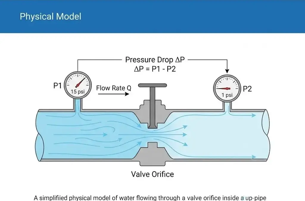
In the complex world of fluid dynamics and industrial piping design, the concept of the valve flow coefficient (Cv) stands as the ultimate dimensional bridge between theoretical mathematics and real-world mechanical performance. But what exactly is it? In standard industrial terms, the flow coefficient cv is defined as the volume of water at exactly 60°F (15.6°C) in US gallons per minute (GPM) that will flow through a fully open valve with a pressure drop of exactly 1 psi across it. It is not merely a theoretical number; it is the physical boundary that protects your pipeline from operational disaster.
Think of the cv rating valve as the width of lanes on a major highway. More lanes allow more traffic to pass freely without causing congestion. However, if you miscalculate this required width in a chemical or water treatment plant, the consequences are severe. If the cv value of valve is too small, fluid velocity spikes dramatically across the narrow restriction, generating intense friction, noise, and potentially destroying the valve trim. Conversely, if the flow coefficient of valve is excessively large, the valve will operate almost closed. This causes the system to lose all control accuracy, leading to severe flow oscillations and premature wear of the actuator components.
Understanding the fundamental nature of the cv value for valves means recognizing that it acts as the energy consumption limit for your pipeline system. Every control valve coefficient must be carefully aligned with the specific gravity and thermodynamic properties of the fluid it aims to regulate.
The Universal Sizing Formula for Liquid Applications
To eliminate sizing errors, engineers globally refer to the international ISA-75.01.01 standard for fluid control equations. This establishes an absolute technical authority for how we calculate valve cv. While the core equation may look straightforward, the application of its variables requires strict engineering discipline.
Breaking Down Flow Rate, Specific Gravity, and Pressure Drop
Liquid Sizing Formula:
Cv = Q × √(SG / ΔP)
In this essential cv formula valve, each variable carries distinct physical weight. Q represents the Flow Rate in US Gallons per Minute (GPM). SG stands for the Specific Gravity of the fluid. A critical mistake many novice designers make is forgetting that Specific Gravity is not a static number—it changes drastically with temperature. Water at 60°F has an SG of 1.0, but near boiling, its SG drops. Finally, ΔP represents the allowable Pressure Drop (P1 – P2) in psi. It is vital to correct the misconception that a higher pressure drop is better. In reality, pressure drop is the specific “energy consumption quota” assigned to the valve by the overall process design.
Executing a Real-World Plant Cooling Water Calculation
To illustrate, let us execute a practical calculation. Assume we are designing a cooling water loop for a chemical processing facility. The known parameters are: fluid temperature is 80°C (176°F), the inlet pressure (P1) is 150 psi, the maximum allowable pressure drop (ΔP) is 15 psi, and the required flow rate is 250 GPM. According to engineering steam tables, the Specific Gravity of water at 80°C is no longer 1.0; it drops to approximately 0.972.
Step 1: Identify variables: Q = 250, SG = 0.972, ΔP = 15.
Step 2: Calculate the ratio of SG to ΔP: 0.972 / 15 = 0.0648.
Step 3: Find the square root: √0.0648 ≈ 0.2545.
Step 4: Multiply by Flow Rate: Cv = 250 × 0.2545 = 63.6.
The theoretical calculated cv of valve is 63.6. However, this is merely a paper calculation. Simply purchasing a valve with a max capacity of 63.6 would be a massive engineering error, as we will explore in the flow characteristics section later. Whether you are assessing a globe valve loss coefficient or a ball valve flow coefficient, safety margins must be applied.
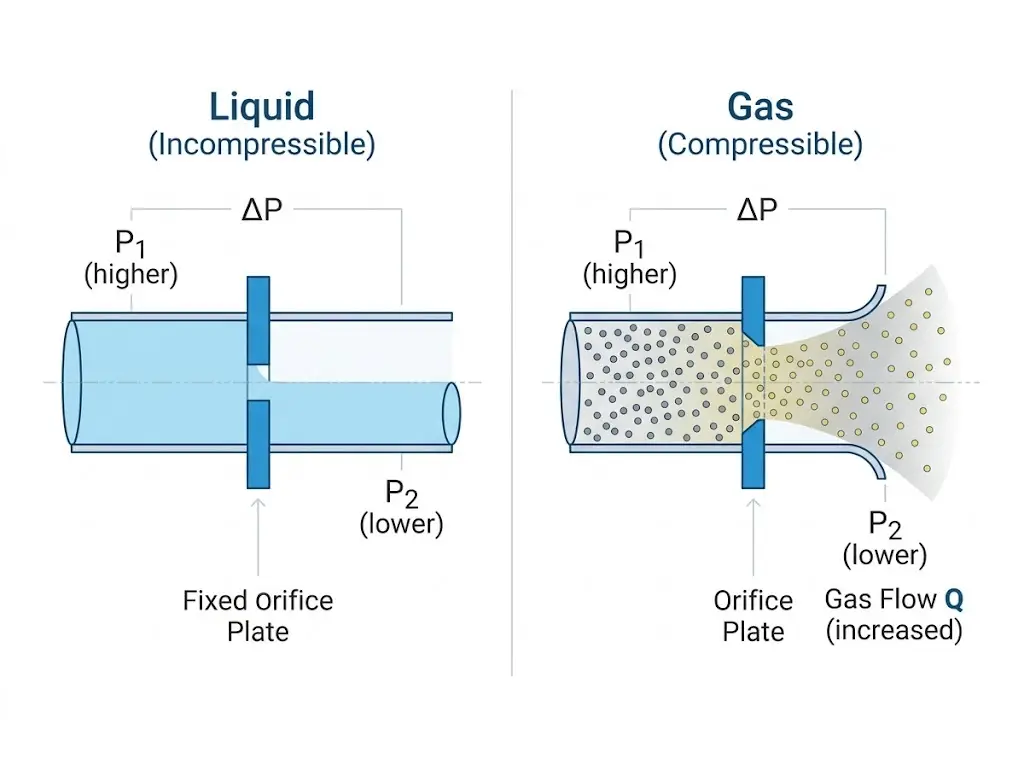
Sizing for Compressible Fluids: Gas and Steam
When dealing with gases and steam, the physics shift dramatically. Compressible fluids expand as their pressure drops, meaning the standard liquid formula is completely inadequate. To correctly calculate control valve cv for compressible media, you must classify the flow as either Subsonic (Non-choked) or Sonic (Choked).
1. Subsonic Flow (Non-choked) Formulas:
Used when pressure drop (ΔP) is less than half the absolute inlet pressure (P1/2).
Cv = (Q / 963) × √[ (SG × T) / (ΔP × (P1 + P2)) ]
2. Sonic Flow (Choked) Formulas:
Used when pressure drop (ΔP) is greater than or equal to half the absolute inlet pressure (P1/2).
Cv = (Q / (816 × P1)) × √(SG × T)
*Note: Q = Flow rate in SCFH, T = Absolute Temperature in Rankine, P1/P2 = Absolute pressures in psia.
For gas applications, the absolute inlet pressure (P1) and the absolute temperature (T) heavily influence the fluid density. When sizing for steam, the rules change again. Saturated steam behaves differently from superheated steam, requiring specific superheat correction factors. Using a generic air equation for a high-pressure boiler system will inevitably result in selecting an undersized valve, leading to catastrophic steam starvation across the facility.
Hidden Sizing Traps: Cavitation and Choked Flow
Believing that standard mathematical formulas are the only tool you need is the most dangerous trap in fluid control. The physical reality of fluid dynamics often overrides paper calculations, especially when dealing with high pressure differentials.
The Critical Role of Liquid Pressure Recovery Factor
As fluid passes through the narrowest restriction inside a valve—known as the Vena Contracta—its velocity accelerates rapidly, causing the localized pressure to plummet. Once past the restriction, the fluid slows down, and pressure partially recovers. The extent of this recovery is measured by the Liquid Pressure Recovery Factor (FL). If the pressure at the Vena Contracta drops below the vapor pressure of the liquid, vapor bubbles form instantly.
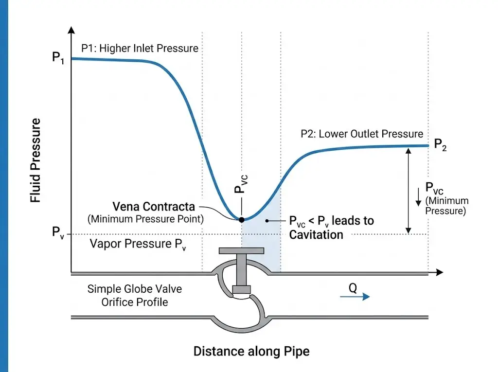
As pressure recovers downstream, these bubbles implode with massive shockwaves—a phenomenon known as cavitation. Cavitation acts like miniature explosions, capable of tearing apart solid stainless steel valve trims in a matter of weeks, leading to unplanned shutdowns costing upwards of $10,000 to $50,000+ per hour in lost production and equipment damage.
Preventing Vapor Pressure Disasters Through Multi-Dimensional Sizing
Once a system enters a state of choked flow (where decreasing downstream pressure no longer increases flow rate due to fluid vaporization), standard equations fail entirely. This highlights why purely theoretical sizing is insufficient for complex industrial environments.
As industry-leading automation valve experts, VINCER mandates an exclusive 8-Dimensional Sizing Analysis (incorporating Media, Temperature, Pressure, Connections, Control Methods, Material Requisites, Industry Standards, and Space constraints) for every client evaluation. If our engineering team detects severe pressure drops that risk cavitation, calculating the flow coefficient cv is only the baseline. Leveraging our extensive 50+ material library we engineer targeted, wear-resistant replacement strategies to eradicate the root causes of leakage and recurring replacements.
Translating Calculated Cv to Valve Flow Characteristics
Once the mathematical baseline is established, you must align the calculated cv for valves with actual hardware procurement parameters. A common mistake is selecting a valve whose maximum capacity exactly matches your calculated requirement.
The Optimal Control Range Principle
In professional procurement, you must adhere to the 20% – 80% opening rule. A control valve should operate between 20% and 80% of its stroke under normal operating conditions. Selecting a valve that requires 95% opening to meet your cv flow coefficient leaves zero safety margin for process fluctuations.
Applying the rule to our previous example: Recall our cooling water calculation that yielded a theoretical requirement of 63.6 Cv. If we apply the 80% maximum opening principle (63.6 ÷ 0.8 = 79.5), the reality is that you should source a control valve with a rated capacity of approximately 80 Cv to ensure stable, long-term regulation.
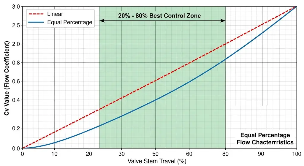
Selecting Between Linear, Equal Percentage, and Quick Opening
| Characteristic Type | Flow Behavior | Ideal Applications |
|---|---|---|
| Linear | Flow capacity increases linearly with valve travel (e.g., 50% open = 50% flow). | Liquid level control, constant pressure drop systems. |
| Equal Percentage | Equal increments of travel produce equal percentage changes in flow. | Systems with varying pressure drops, most temperature/pressure control loops. |
| Quick Opening | Maximum flow capacity is reached very early in the valve travel. | On/off service, safety relief. Not suitable for throttling. |
Whether you are evaluating a butterfly valve flow coefficient curve or standard globe valves, matching the inherent characteristic to your system dynamics ensures smooth, oscillation-free automation.
Global Procurement: Converting Between Cv and Kv Standards
In global engineering projects, converting between the American standard (Cv) and the European standard (Kv) is a daily necessity. While Cv uses US gallons and psi, Kv measures water flow in cubic meters per hour (m³/h) at a 1 bar pressure drop. Misunderstanding the cv kv valve relationship can lead to undersizing a valve by nearly 15%, a costly procurement error.
Cv = 1.156 × Kv
Kv = 0.865 × Cv
Procurement teams must always double-check the manufacturer’s origin data sheet to confirm which metric is being presented before finalizing any automation control valve purchases.
Engineering Best Practices for Final Valve Selection
Before placing an order, run your findings through a final engineering checklist: Have you corrected Specific Gravity for operating temperature? Have you calculated Cv across minimum, normal, and maximum flow scenarios? Have you verified the Liquid Pressure Recovery Factor (FL) against your system’s vapor pressure?
It is always better to calculate three times than to halt production to replace a mismatched pipeline. However, for engineers managing severe environments like desalination, CIP cleaning systems, or demanding chemical processing, arriving at the correct flow coefficient is only the first step. Finding a dependable manufacturing partner is the ultimate safeguard.
With over 10 years of dedicated industry experience and comprehensive CE/SIL/FDA certifications, VINCER is positioned as your ultimate one-stop intelligent valve solutions provider. Our specialized engineering team of over 10 experts operates with unmatched agility, providing precise quotes for simple solutions within 24 hours, and delivering preliminary project solutions for multi-product systems within 48 hours.
Supported by a completely autonomous manufacturing infrastructure that spans from raw casting to CNC precision finishing, we confidently stabilize lead times for standard automated valves at a rapid 7-10 working days. Through exhaustive condition evaluations and premium material matching, we eliminate the risks of internal leakage, recurring maintenance, and unplanned facility shutdowns—fundamentally optimizing your Total Cost of Ownership (TCO).
*Missing some system parameters? No problem—submit the data you have, and our fluid dynamics experts will help you calculate the rest for free.