引言
在风险极高的工业自动化领域,无论您管理的是大型多级海水淡化厂、卫生要求严苛的食品加工厂,还是结构复杂的高压石化管道,操作失误的容错空间实际上为零。流经系统架构的每种流体、易挥发气体或磨蚀性浆料,都必须以绝对且毫不动摇的精度加以控制。这一自动化控制系统的核心,是一种能够将原始、未经精炼的能量转化为精确、可重复的机械运动的机制。在现代工程师可用的浩如烟海的技术中, 齿条和齿轮式阀门执行器 在可靠性、速度和容积效率方面,堪称无与伦比的工程奇迹。.
然而,为高度专业化的管道选择正确的执行器,绝非仅仅是匹配管径这样简单粗浅的问题。资深项目工程师和工厂采购经理经常遇到系统灾难性故障、密封件过早磨损以及维护成本呈指数级飙升的情况,而这些问题往往仅仅源于初始选型不当、忽视压力降额,或是对执行器内部机械原理和材料兼容性的理解不充分。本终极指南旨在深入剖析这些设备的“技术基因”,超越表面定义,深入探讨决定工厂长期运营成功的关键变量——例如扭矩曲线特征、动态摩擦安全系数、管网压降以及以投资回报率(ROI)为导向的选型标准。.
什么是齿条和齿轮执行器?
为了彻底揭开这一关键组件的神秘面纱,我们必须将其分解为最基本的物理功能。从最严格的机械角度来看,一个 齿条和齿轮执行器 这是一种结构坚固的装置,旨在根据具体的工业应用需求,将直线运动(由气压或电动力产生的沿直线方向的运动)无缝且高效地转换为旋转运动(围绕固定轴线的旋转运动),反之亦然。.
在过程自动化和流体控制这一专业领域,它专为维护和控制而设计 “四分之一转”(0°至90°)阀门. 其中最常见的例子包括工业球阀、高性能蝶阀和旋塞阀。这些类型的四分之一转阀只需精确旋转90度,即可从全开、最大流量状态完全过渡到全闭、气泡级密封的关闭状态。当可编程逻辑控制器(PLC)或分布式控制系统(DCS)发送电子指令时,执行机构便会克服管道介质产生的巨大摩擦力,完成旋转阀杆这一繁重的体力劳动。.
运动学方向盘类比
为了直观地理解内力,不妨想象一下传统汽车的转向系统。当你转动方向盘(旋转输入)时,与转向柱相连的小齿轮会沿着装有精密齿牙的直线轨道(齿条)转动。这一动作会推动齿条向左或向右移动,从而使车轮转动。工业 执行器齿条和齿轮 该系统遵循完全相同的基本机械原理,但能量流向发生了逆转:巨大的线性力(由压缩空气提供)推动齿条,从而迫使中央小齿轮旋转,进而以巨大的扭矩驱动阀杆转动。.
核心原理:齿条和齿轮执行器如何转换运动
要诊断潜在的现场故障并确保初始规格正确,彻底理解铝制壳体内部确切的热力学原理和齿轮运动学至关重要。虽然总体机械原理保持不变,但工作顺序完全取决于驱动动力源。我们必须分析渐开线齿轮轮廓如何在高频运行下保持零背隙,以及压力差如何在气缸内完成精确的机械功。.
直线运动转动转换(气动驱动)
过程自动化中的绝大多数应用完全依赖于 气动齿条和齿轮执行器. 这些特定设备利用压缩仪表空气的势能来产生巨大的线性推力。现代工业设计的真正精妙之处在于一种平衡的机械结构,工程师们将其称为 “对置活塞设计”.
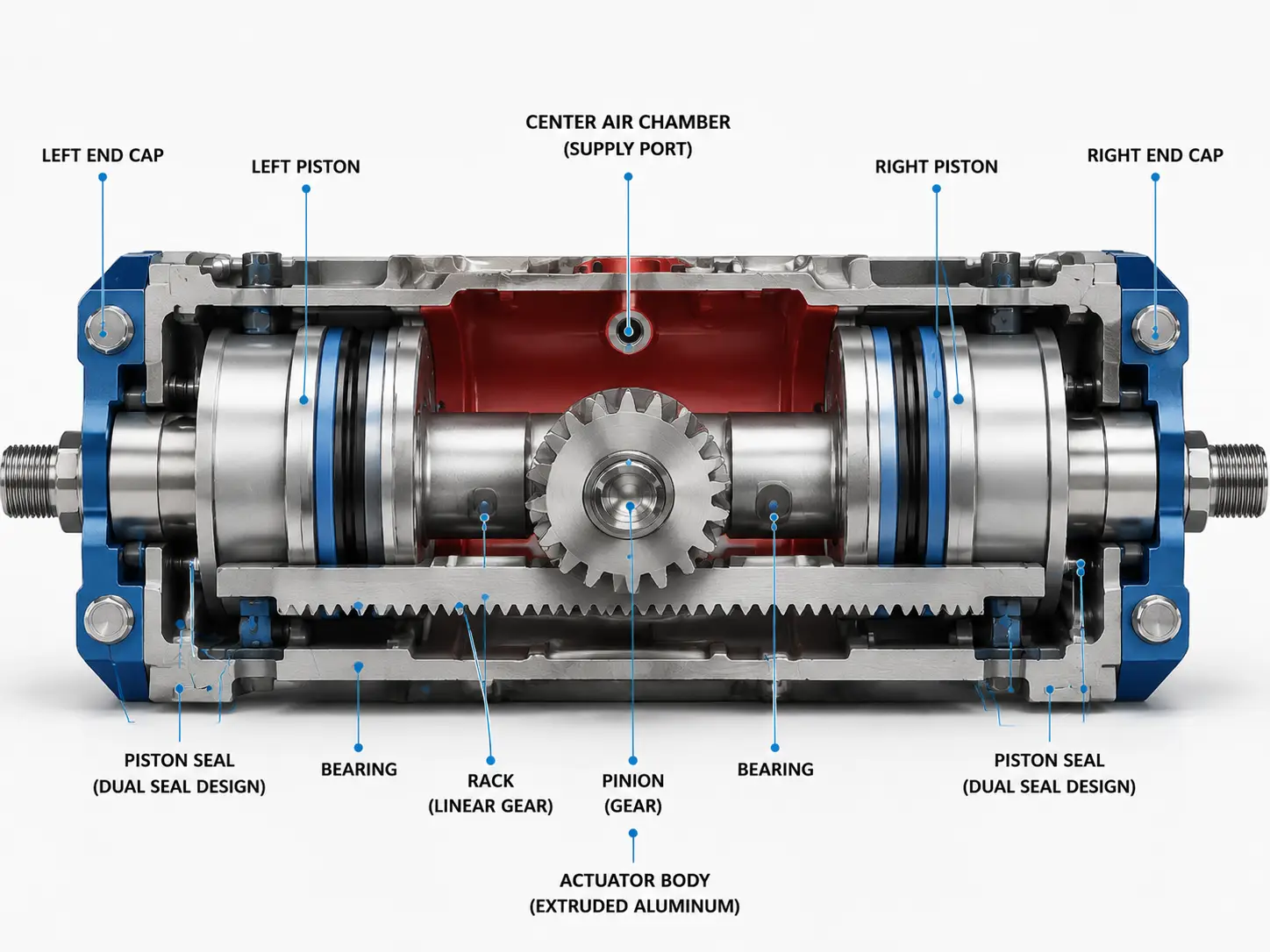
要理解这些设备为何如此可靠,我们必须逐步分析其驱动循环的物理过程,追踪空气从压缩机到最终机械输出的路径:
- 加压与质量注入: 干净、干燥的压缩空气通过一个标准螺纹接口(通常符合NAMUR标准)直接进入执行器外壳的中央腔室。这一高度动态的过程依赖于连续的质量注入和压差平衡。当压缩机将空气质量压入封闭腔室时,会形成一个高压区,该区域会积极地与环境压力以及活塞的静态机械摩擦力相互作用以达到平衡。.
- 线性位移: 这种巨大的压差均匀地作用在两个相对的活塞的表面上。根据物理学的基本原理, 力 = 压力 × 面积, 压缩气流推动两个活塞向外移动,沿一条完全笔直的直线相互远离,朝向端盖。.
- 旋转啮合(渐开线齿形): 每个活塞的内侧都装有一个一体式、经精密加工的直线齿轮,称为“齿条”。这些齿条采用精密的渐开线齿形,以确保完美的啮合和极低的背隙。当活塞沿相反方向作直线运动时,齿条会同时使小齿轮逆时针旋转,从而打开阀门。.
对置活塞设计是平衡动载荷的绝对工程必要条件。通过让两个活塞同时从小齿轮的严格相对两侧施加推力,侧向载荷在数学上得以完美抵消。这产生了极具对称美感、高度稳定且恒定的扭矩输出,确保阀杆不会受到破坏性的侧向弯曲力作用。不妨想象两名体重相同的相扑选手背靠背站立,朝相反方向用力推动一个巨大的旋转闸门——整个结构在轴线上始终保持着完美的平衡。.
旋转运动到直线运动的转换(电机驱动)
虽然工业流体控制领域几乎完全依赖线性-旋转转换原理来驱动四分之一转阀,但该机构的几何原理在机械上完全可逆。为了认识到其在工厂自动化中的更广泛应用,有必要简要探讨其反向功能。在此配置下——这种配置在蝶阀中是不会出现的——能量流向发生了逆转。.
一个旋转动力源——通常是电动伺服电机——直接连接到中央小齿轮上。当电机驱动小齿轮旋转时,齿轮会沿固定的线性齿条移动,从而将旋转能转化为精确的线性定位。虽然你不会在驱动管道蝶阀的装置中看到这种反向配置,但这一原理却是现代制造车间中自动化线性导轨、机器人传输臂和龙门定位系统的机械核心,彰显了齿条与小齿轮机械概念的非凡通用性。.
双作用与弹簧复位执行器
一旦确立了基础动力机制,流体控制工程师在职业道路上面临的下一个关键抉择便涉及管道安全与灾难性失效模式的规划。倘若在恶劣天气事件、电网大面积停电或局部压缩机故障期间,工业系统突然失去压缩空气压力或电力供应,阀门的位置会发生什么变化?这一根本性的安全问题决定了在 执行器齿条和齿轮 组装。.
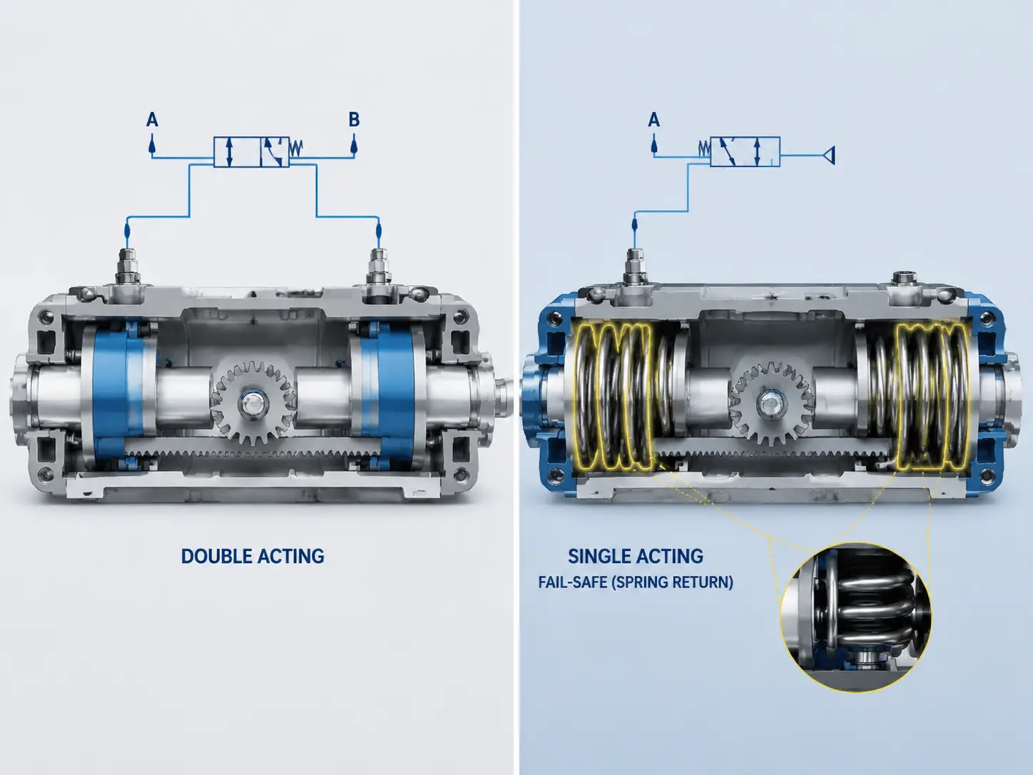
双作用:最大化对称扭矩
双作用气动执行器完全依赖于压缩空气的持续供应,以完成阀门行程中的开启和关闭两个循环。要开启阀门,外部电磁阀将空气导入中央腔室,从而强行将相对的活塞向外推。要关闭阀门,电磁阀先将中央腔室中的空气排空,同时将高压空气重新导向两个外端盖,从而将活塞向内推回其初始位置。.
由于在整个工作循环的任何阶段,都没有笨重的机械弹簧与膨胀的气压相抗衡,因此双作用 齿条和齿轮式阀门执行器 利用100%的升力来产生旋转功。这使得该装置能够在0°至90°的整个旋转行程范围内,提供完全恒定、对称且可预测的扭矩输出。此外,由于无需安装大型弹簧组,双作用装置的结构更为紧凑,且初始投资成本更低。.
理想的工程场景: 这种双作用配置具有极高的成本效益,非常适合非关键流体系统,例如标准冷却水回路、低风险混合罐或非危险性公用管线。在这些特定应用中,即使工厂气压突然丧失导致阀门卡死并保持在“最后位置”(原位失效),也不会引发灾难性的环境泄漏,也不会危及工厂安全。.
关键工程说明: 请注意,为了在巨大的动态变化下成功维持这种“就地故障”状态, 流体动力扭矩 由于高速流体从阀盘旁高速流过,真正的空气失效系统必须明确配备一个 气锁阀. 这一关键配件可将气动回路完全密封,将气缸内的残余压力物理锁定在内部,从而防止流体动力作用导致阀门打开。.
弹簧复位:关键系统的故障安全机制
相反,对于危险环境、高压蒸汽管线或有毒化学品管道,根据国际安全规范和SIL(安全完整性等级)指令,必须使用弹簧复位式执行器。在此高度复杂的机械设计中,气压仅用于将活塞推向一个方向(通常是打开阀门)。当活塞向外移动时,它们会同时压缩一组安装在伸出的端盖内的重型高抗拉强度机械弹簧。.
如果气源意外中断,这些压缩弹簧中储存的机械势能会立即接管,无需任何外部动力,自动将活塞推回其原始静止位置。在石油化工和油气行业,这被正式定义为“失效安全”机制。根据执行器与阀杆的物理安装方式,该机制可配置为“失效关闭”(立即切断易燃气体的流量以隔离泄漏)或“失效开启”(立即打开泄压阀,以安全地释放过热反应釜内的压力)。.
水锤风险与水力阻尼
一种非常普遍且极其危险的工程误解是:认为在断电时,应允许弹簧复位式失效安全装置瞬间“弹开”或“猛然”关闭阀门,以尽可能快地停止流体流动。在高压液体管道中,阀门的瞬间关闭会在流体柱内产生巨大的超音速动能冲击波,这被称为 ‘水锤’效应 (或流体瞬态)。这种巨大的压力骤升实际上会将焊接管法兰撕裂,严重损坏垫片,并永久性地损坏昂贵的上游离心泵。.
为了防止这种灾难性的动能传递,高品质的气动执行器系统必须经过专门设计,以减缓弹簧力的作用。这可以通过安装经过校准的排气节流阀(通过限制排气气流形成气动缓冲)或外部液压阻尼器来实现。这些关键附件能主动抵消弹簧的剧烈扩张,从而减缓行程末段的速度。这确保了流体柱能够以安全、数学可控的方式减速,而非发生剧烈且具有破坏性的机械撞击。.
技术对比表:双作用式与弹簧复位式
| 工程维度 | 双作用(DA)配置 | 弹簧复位(SR)配置 |
|---|---|---|
| 工作电源(开启/关闭) | 压缩空气 / 压缩空气 | 压缩空气/机械弹簧扩张 |
| 扭矩输出曲线 | 在整个90°旋转行程中保持恒定且完全对称。. | 变量(扭矩在最大压缩时达到峰值,在“弹簧末端”时最弱)。. |
| 故障安全能力 | 就地失效(需配备专用外部气锁阀以保持位置)。. | 一旦电源或气源中断,立即自动“故障闭合”或“故障常开”。. |
| 物理尺寸与重量 | 端盖结构极为紧凑;整体单件重量显著降低。. | 需要加长的端盖以容纳重型弹簧组;重量更重。. |
| 理想的工业应用 | 标准冷却水回路、低风险混合罐、通用管线。. | 石化管道、高压蒸汽、有毒气体、SIL等级的安全回路。. |
气动与电动配置的对比及投资回报率优化
虽然机械内部结构决定了安全性,但主要动力源的选择则决定了工厂的长期经济可行性。项目工程师们经常在气动和电动动力配置之间难以抉择。要做出正确的选择,必须将目光投向初始采购订单之外,并进行严格的 总体拥有成本(TCO) 针对多年时间跨度的分析。.
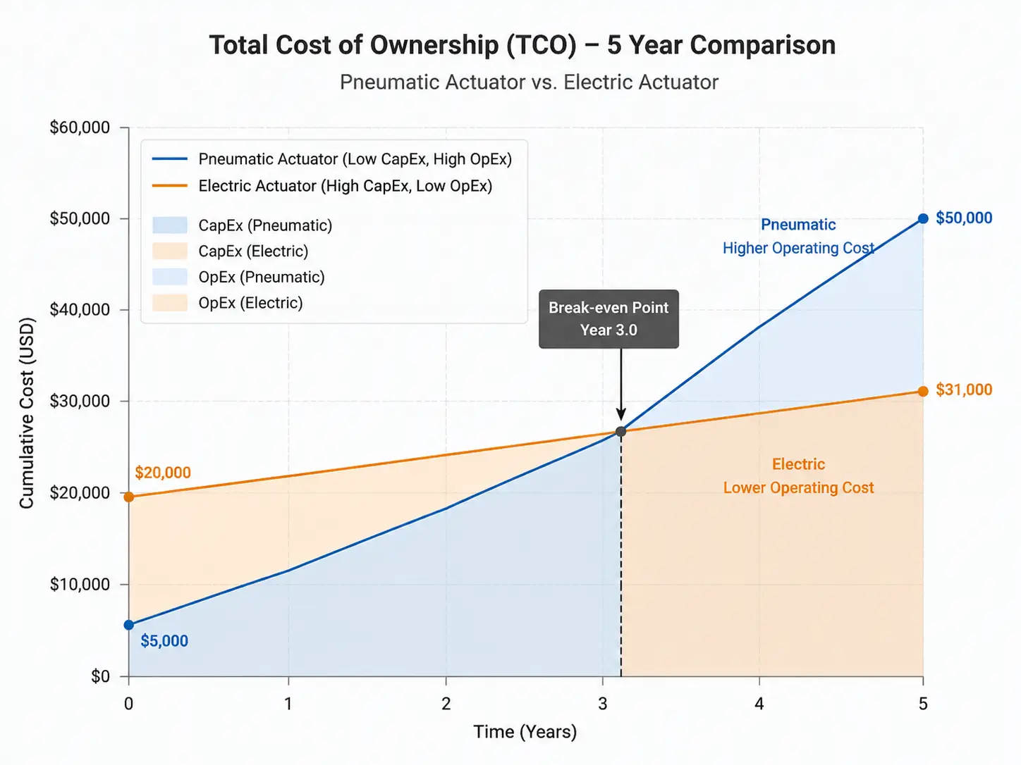
在为新工厂评估自动化解决方案时,采购团队往往对电动执行器的初始资本支出(CapEx)过高而望而却步,其价格往往比气动执行器高出3到5倍 齿条和齿轮执行器 同类产品。因此,气动系统在市场上占据主导地位。然而,气动系统的运行绝非“免费”。它们需要工业空气压缩机,而这类设备本质上属于效率较低的热力学机器。在典型的制造工厂中,压缩机消耗的电能中多达30%会因发热而瞬间损失,另有10%至20%的电能通常会通过老化的管道网络中的微小泄漏而流失。.
如果某设施尚未配备强大且大容量的压缩空气基础设施,或者控制阀距离主压缩机房有几公里之遥,仅为维持管路气压所需的持续电力成本就会呈指数级飙升。行业能源审计一再表明,存在一个明显的经济临界点:
• 一台标准的气动执行器前期成本可能仅为 $300,但每年因持续使用压缩空气而产生的电费高达 $500(这是由于 20% 的电网损耗以及压缩机固有的效率低下所致),总计 $2,800,分5年支付.
• 一台同等性能的电动执行器,前期成本可能为 $1,500,但在高度间歇性、按需供电的情况下,每年仅消耗 $50 的电费,总计 $1,750,分5年支付.
财务结果:资本支出(CapEx)与运营支出(OpEx)的盈亏平衡点通常出现在第36个月左右,此后,该电力配置将带来纯粹的成本节约。.
相反,如果该工厂已经拥有一个规模庞大、高效且维护良好的压缩空气网络(例如在大型集中式化工炼油厂中),那么 气动齿条和齿轮执行器 凭借其极低的维护要求、极快的驱动速度以及低廉的部件更换成本,它依然是投资回报率(ROI)方面的无可争议的冠军。.
解读扭矩曲线与选型
缺乏经验的采购团队最常犯且对财务造成最严重破坏的错误是选择 齿条和齿轮执行器 仅凭产品目录中列出的“最大输出扭矩”与阀门的额定要求相匹配这一标准。由国际自动化协会(ISA)等严谨机构指导的专业流体控制工程,要求对动态扭矩曲线和实际运行变量进行更为深入的数学分析。.
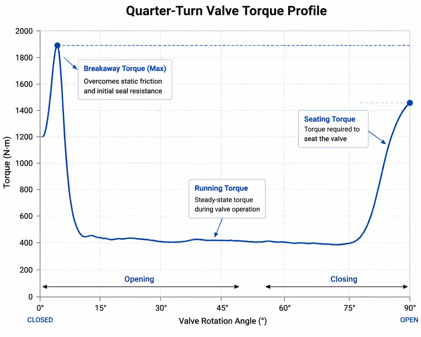
了解起步扭矩、行驶扭矩和终末扭矩
当您在管道带压状态下操作工业阀门时,所需的物理力绝非一条平坦且恒定的曲线。试想一下,用物理动力学原理来推开一扇沉重且略带锈迹的铁制保险库门。为了克服密封件的静摩擦力并使球阀或碟阀的阀芯脱离阀座,最初所需的巨大动能推力是极其巨大的——这普遍被称为 脱开扭矩. 一旦阀门开始运动,流动流体产生的水动力通常会推动其继续运动,因此所需的机械力要小得多(Running Torque). Finally, to firmly snap the valve shut, compress the elastomer seats against the pipeline pressure, and achieve a bubble-tight seal, an extra terminal surge of force is needed (Ending/Seating Torque).
For a spring return pneumatic actuator, we must also factor in Hooke’s Law of elasticity. As the heavy-duty springs physically extend to close the valve, their mechanical pushing force linearly decreases. Therefore, the absolute weakest point of the actuator’s entire mechanical cycle is the “Spring End Torque” (the final pushing force the springs can generate at the exact moment the valve reaches 0°). If this specific mechanical value drops below the valve’s required Seating Torque, the valve will simply not close tightly, leading to highly dangerous internal media leakage across the closed pipeline.
Calculating the Crucial Safety Factor
The baseline torque values published by valve manufacturers are tested in sterile laboratory conditions using clean water at ambient temperatures. The real industrial world is entirely unforgiving. Therefore, applying a calculated Safety Factor is a non-negotiable engineering requirement to prevent actuator stalling during critical operations.
Advanced Sizing Guidelines & Network Pressure Derating:
- Media-Specific Safety Factors: For clean, naturally lubricating fluids (e.g., filtered water, light hydraulic oils), engineers must add a minimum 20% to 30% safety factor to the baseline torque. For dry, non-lubricating gases or high-temperature steam, add 30% to 40%. For highly abrasive slurries or dry powders, a safety factor of 50% or higher is mandatory, as particulate buildup will severely increase the friction on the valve trim over its lifecycle.
- The Pressure Drop Derating Trap: Never size an actuator based on the optimal air pressure generated inside the main compressor room. If a factory specifies a nominal 5 bar (72 psi) air supply, the actual aerodynamic pressure at the very end of a long, complex pipe network during peak facility usage might severely drop to 4 bar (58 psi). Because a pneumatic actuator’s torque output is directly and linearly proportional to the supplied air pressure, a pressure drop from 5 bar to 4 bar results in an instant 20% loss of output torque. Professional rule of thumb: Always calculate your actuator size based on the minimum guaranteed worst-case pressure at the valve’s specific pipeline location, never the theoretical maximum.
Failure Modes, Seal Degradation, and Maintenance
Even the most robustly constructed mechanical devices will eventually face the harsh realities of industrial wear and tear. To achieve a MECE (Mutually Exclusive, Collectively Exhaustive) understanding of actuator failure modes, engineers must strictly separate the internal mechanisms from the external atmosphere. The internal mechanism of an actuator only ever processes compressed air, while the attached valve handles the actual pipeline fluid. Therefore, actuator failures are dictated by three distinct physical modes.
First, internally, the most prevalent “silent killer” in pneumatic automation is dynamic seal degradation. If the facility’s compressed air is unlubricated, excessively hot, or contaminated, standard NBR (Nitrile) piston O-rings will rapidly harden, crack, and cause “blow-by” (air leaking past the piston, resulting in severe torque loss). Second, externally, harsh atmospheric conditions—such as heavy salt spray on offshore oil rigs or caustic washdowns in food plants—will chemically attack the aluminum housing, causing severe pitting and structural decay. Finally, from a pure kinematic perspective, high-frequency actuation (millions of open/close cycles) will eventually lead to microscopic fatigue wear on the gear tooth meshing surface between the rack and the pinion, increasing backlash and severely reducing positioning accuracy.
Mitigating Risk Through Comprehensive 8-Dimension Engineering
To eliminate these multi-faceted failure modes at the source, professional industrial automation providers abandon the basic “one-size-fits-all” catalog approach. For instance, Vincer Valve, a recognized high-tech enterprise with over a decade of dedicated fluid control expertise, employs an industry-leading 8-Dimension Analysis Methodology for every single project requirement. Before any manufacturing begins, their dedicated engineering team rigorously evaluates the Medium, Temperature, Pressure, Connection Standard, Control Method, Material Requirements, Industry Characteristics, and precise Installation Space.
Drawing from an extensive, highly customizable inventory of over 50 specific material combinations, the actuator is matched perfectly to both its internal duty cycle and its external environment. For example:
- Internal Dynamic Resilience: To combat high-frequency friction heat and ensure long-term reciprocating performance without blow-by, Vincer upgrades the internal piston seals to premium imported FKM, drastically outlasting standard seals in demanding, high-temperature pneumatic environments.
- External Environmental Armor: For highly corrosive external atmospheres, such as offshore marine platforms exposed to constant salt spray, standard extruded aluminum is insufficient. Vincer mitigates this by offering specialized anti-corrosion epoxy coatings, or entirely upgrading the housing to SS316L stainless steel. This ensures the actuator’s structural integrity remains uncompromised even in the most brutal ambient atmospheres.
Industry Standards and Interface Configurations
Finally, a perfectly sized and brilliantly engineered actuator is completely useless if it cannot physically connect to your valve or communicate with your digital control network. The industrial automation sector has strictly standardized these mechanical and pneumatic connections to ensure modular compatibility across global equipment brands. When specifying your 执行器齿条和齿轮, ensure absolute conformance to these primary interfaces:
- ISO 5211 (The Mechanical Foundation): This is the universal global standard specifying the exact bolt circle dimensions of the bottom mounting flange and the geometric shape of the drive shaft (usually a star or square drive). This guarantees the actuator will mate flawlessly to the top of the valve stem without wobbling or introducing mechanical hysteresis.
- NPT or BSP (The Air Supply): Depending on your geographical region (North America heavily utilizes NPT threads, while Europe and Asia default to BSP), ensuring the correct thread standard on the pneumatic ports prevents frustrating air leaks and cross-threading during site commissioning.
- NAMUR (The Automation Ecosystem): NAMUR standardizes the mounting patterns for all external automation accessories, essentially transforming a “dumb” mechanical cylinder into a “smart”, fully integrated automated node.
To create a complete closed-loop control system, an actuator relies on two critical NAMUR accessories:- The Solenoid Valve (The Brain): Bolted directly to the standardized side NAMUR interface, the solenoid valve receives the low-voltage electrical command (e.g., 24VDC) from the PLC and physically redirects the high-pressure compressed air into the correct actuator chamber to open or close the valve.
- The Limit Switch Box (The Eyes): Mounted securely to the top NAMUR pinion shaft, this electromechanical device physically tracks the actual rotation of the actuator. It sends a continuous electronic signal back to the DCS/control room, providing absolute, real-world confirmation that the valve has successfully reached its intended fully open or fully closed position.
Secure Your Pipeline’s Future with Uncompromising Precision
Ensure the long-term reliability of your fluid control systems by partnering with a manufacturer that prioritizes extreme engineering precision and intelligent solution design.
Operating under strict ISO9001, CE, RoHS, SIL, and FDA certifications, Vincer Valve guarantees that every component meets rigorous international standards. With an agile supply chain capable of delivering standard configurations in just 7 to 10 working days—and providing comprehensive technical proposals within 24 to 48 hours—Vincer is uniquely positioned to accelerate your project deployment without sacrificing engineering quality.
Consult a Vincer Engineer Today