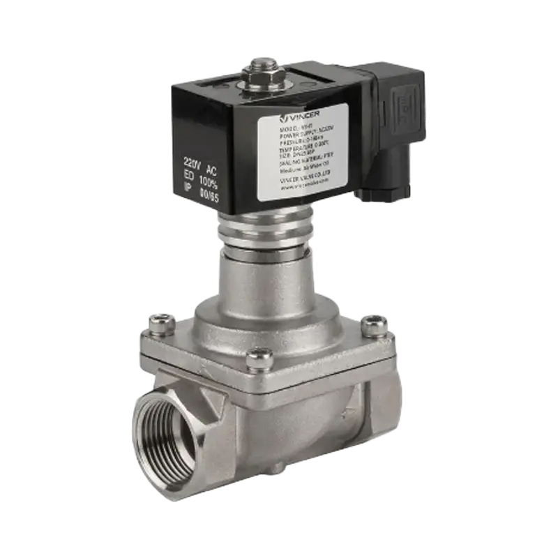
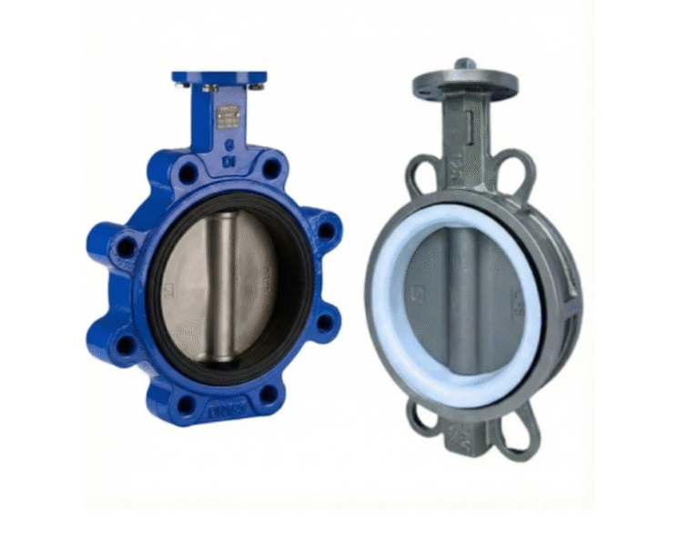
Каждый раз, когда вы видите клапан-бабочку в линии водоподготовки, техническом помещении системы отопления, вентиляции и кондиционирования, градирне или химической установке, вы смотрите на одно из самых простых устройств в промышленных трубопроводах: диск на валу, который поворачивается на четверть оборота для открытия и закрытия. Как работает дроссельная заслонка? Описание механизма занимает всего два предложения. Чтобы понять, на что она способна, а на что нет, потребуется остальная часть этой статьи: мы рассмотрим сам поворот на 90°, затем типы, которые от него ответвляются, вопрос об автоматизации и, наконец, условия, при которых принцип работы перестает действовать.
Что такое клапан-бабочка и как он работает?
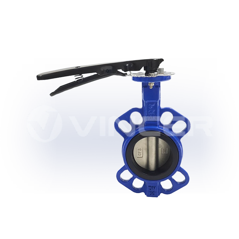
Дроссельный клапан — это клапан с поворотом на четверть оборота, который перекрывает или регулирует поток за счет вращения диска вокруг центрального штока. “Бабочка” — это и есть этот диск. Когда клапан полностью открыт, диск располагается параллельно направлению потока; когда он полностью закрыт, он поворачивается на 90°, принимая перпендикулярное положение и перекрывая проход (Википедия). Поскольку полный ход составляет всего 90°, клапан открывается и закрывается быстрее, чем многооборотные типы, такие как задвижки.
Этот принцип состоит из четырёх частей:
- Основная часть — корпус, устанавливаемый между фланцами труб (типа «вафля», с выступом или с двумя фланцами).
- Диск — закрывающий элемент; поворачивается для перекрытия или пропуска потока.
- Стебель — передаёт вращение от рукоятки или привода на диск.
- Сиденье — уплотняющая поверхность, к которой прижимается диск в закрытом положении.
Его ближайшим аналогом является шаровой кран: оба устройства относятся к категории поворотных на четверть оборота и открываются и закрываются за один поворот на 90°. Разница, определяющая все последующие инженерные решения, заключается в том, что шарик шарового крана при открытии уходит из потока, в то время как диск дроссельной заслонки остаётся в потоке. Именно этот конструктивный особенность не позволяет отнести дроссельный клапан к клапанам с полным проходом: в открытом состоянии он всегда создаёт некоторое сопротивление, а трубопроводы, в которых он установлен, невозможно очищать с помощью скребковых скребков. Это цена, которую приходится платить за лёгкость, компактность и значительно более низкую стоимость по сравнению с другими клапанами больших диаметров, и именно этот факт определяет физику уплотнения, типы отводов и пределы дросселирования, о которых пойдёт речь далее в этой статье.
Типы клапанов-бабочек: три конструктивных слоя, один принцип действия
Существует ровно один принцип действия и множество типов. Каждый “тип” клапана-бабочки представляет собой один и тот же механизм с углом поворота 90°, в котором изменен один конструктивный элемент: как диск прилегает к седлу, как клапан устанавливается в трубопровод и из чего изготовлено седло. Ознакомьтесь с тремя уровнями, приведёнными ниже, и вы сможете отнести любую доступную на рынке дроссельную заслонку к одному из них: какой вариант является стандартным, какой — основным, а какой предназначен для экстремальных условий эксплуатации.
Конструкция уплотнения: концентрическая, с двойным смещением и с тройным смещением
Первый конструктивный слой — это уплотнительное зацепление, то есть то, как диск примыкает к седлу при закрытии. ⭐ Концентрическая конструкция (с нулевым смещением) является наиболее распространённой конструкцией дроссельных клапанов на рынке: его шток расположен на центральной линии диска, и его закрытие напоминает оттиск штампа на бумаге: в конце хода диск скользит по седлу. Такой скользящий контакт вполне подходит для мягких седел, используемых в системах водоснабжения и вентиляции, а также позволяет снизить стоимость клапана. Конструкция с двойным смещением является стандартным решением для линий большого масштаба и при частых циклах работы — шток смещен как относительно центра диска, так и относительно центра отверстия, поэтому диск отрывается от седла в момент открытия, а не скользит по нему. Меньшее трение, меньший износ: именно поэтому в муниципальных водопроводных сетях используются конструкции с двойным смещением. Конструкция с тройным смещением — это редкая разновидность высокотехнологичных решений — третье коническое смещение обеспечивает контакт диска с седлом без какого-либо скольжения, благодаря чему седло может быть изготовлено из твердого металла и обработано таким образом, чтобы обеспечивать герметичное закрытие при высоких температурах, высоком давлении и при работе с углеводородами.
| Дизайн | Как работает уплотнение | Трение и износ | Типичные служебные обязанности | Положение на рынке |
|---|---|---|---|---|
| Концентрический (с нулевым смещением) | Диск прижимается непосредственно к опоре; скользит по ней | Наибольшее трение из всех трёх | Водоснабжение, системы отопления, вентиляции и кондиционирования воздуха, системы низкого давления | ⭐ Наиболее распространённый — стандартный вариант для повседневного обслуживания |
| Двойное смещение | При открытии дисковая заслонка поднимается с седла под действием кулачка | Трение значительно уменьшилось | Большие трубопроводы, повышенное давление, частые циклы работы — водопроводные сети | ⭐ Стандарт для сетевой службы |
| Тройное смещение | Конический контакт «металл-металл», без скольжения | Трение незначительно; износ наблюдается преимущественно при закрытии | Высокие температуры и давление, нефть, газ, химическая промышленность | «Rare» — только по ставке «премиум» |
Одно ограничение, о котором почти никто не пишет: металлическое седло работает надежно только до тех пор, пока клапан полностью закрыт. Если клапан с тройным смещением остается частично открытым, заблокирован мусором или не получает достаточной силы привода из-за слишком маломощного привода, металлическое седло изнашивается, и этот износ невозможно устранить так же, как в случае с эластомером (опыт эксплуатации, форум по проектированию клапанов Eng-Tips).
Типы соединений: вставные, с наконечниками и с двойными фланцами
Второй конструктивный уровень касается способа монтажа клапана в трубопроводе и определяет один важный практический момент: можно ли проводить работы с одной стороны клапана без слива всей жидкости из трубопровода. ⭐ Соединение типа «вафля» (вафельного типа) является наиболее распространённым вариантом: клапан зажат между двумя фланцами с длинными сквозными болтами — конструкция компактная, недорогая, но её невозможно использовать на конце трубопровода. Соединение с наконечниками — это вариант, удобный с точки зрения технического обслуживания: резьбовые вставки с обеих сторон позволяют отсоединять любую из сторон трубопровода независимо друг от друга, поэтому данная конструкция является стандартом для изоляции на конце трубопровода. Соединение с двумя фланцами — это отвод для тяжелых условий эксплуатации: собственные фланцы — для больших диаметров и высокого давления.
При использовании клапана с проушинами следует учитывать одно предостережение: при установке в тупиковой линии его необходимо оснастить глухим фланцем, поскольку в этом случае его номинальное давление снижается — клапан с проушинами, рассчитанный на давление 150 psi при установке между двумя фланцами, при монтаже с одним фланцем выдерживает примерно вдвое меньшее давление (Википедия).
Материал сидений: мягкие сиденья против металлических сидений
Третий структурный слой представляет собой материал, который фактически обеспечивает герметичность, и именно он определяет максимальную допустимую температуру всей конструкции. ⭐ Мягкие сиденья используются в подавляющем большинстве случаев в условиях обычной эксплуатации: при закрытии клапана эластомер (EPDM, NBR, PTFE) слегка деформируется по краю диска, обеспечивая герметичное, зачастую абсолютно герметичное уплотнение при нормальных температурах и давлениях. Металлические сиденья — это наша специализация: диск прижимается к точно обработанной металлической поверхности, что оправдывает себя лишь в условиях высоких температур, высокого давления или в коррозионной среде, где эластомеры вышли бы из строя.
| Материал | Максимальная температура | Стандартные услуги |
|---|---|---|
| ЭПДМ | 120 °C (248 °F) | Питьевая вода — не влияет на вкус |
| НБР | 85 °C (185 °F) | Услуги в сфере нефтяной и водной промышленности |
| FKM | 180 °C (356 °F) | Общая химическая и термическая стойкость |
| ПТФЭ / силикон | 200 °C (392 °F) | Агрессивные среды, работы, связанные с паром |
Если эти значения будут превышены, рабочие характеристики сильфона ухудшаются — по принципу действия диск продолжает вращаться, но клапан перестает обеспечивать герметичность.
Совместив эти три уровня, можно понять, как устроен рынок: стандартным клапаном для повседневного использования является концентрический клапан «бабочка» с мягким седлом; основным рабочим инструментом в сетях служит клапан с двойным смещением и мягким седлом, оснащенный фланцевым соединением, что позволяет осуществлять техническое обслуживание по участкам; а топовой моделью является клапан с тройным смещением, металлическим седлом и двойным фланцем. Выбор клапана «бабочка» в основном сводится к определению того, в каком из этих трех уровней находится ваша эксплуатационная нагрузка.
Вручную или автоматически? Ключевой момент при выборе клапана «бабочка»
Кто поворачивает шток? Это первое реальное решение, которое приходится принимать покупателю, и оно уже не является нейтральным. Один и тот же механизм с углом поворота 90° может приводиться в действие вручную (с помощью рычага или редуктора), сжатым воздухом (пневматический привод) или электродвигателем (электрический привод) — и отрасль постепенно делает автоматизацию стандартом.
Этот сдвиг обусловлен тремя заметными факторами. Во-первых, архитектура системы управления: сети производственных объектов теперь используют в качестве стандартного языка протоколы PLC/SCADA и 4–20 мА, поэтому клапан, которым невозможно управлять из диспетчерской, требует наличия отдельного оператора для ручного управления — это должно быть оправданным исключением, а не нормой. Во-вторых, трудозатраты: клапан с приводом избавляет от необходимости подходить к нему, использовать гаечный ключ и повторно проверять результат при каждой операции с клапаном; предприятия сокращают число операторов, а не автоматизацию клапанов. В-третьих, новые области применения: в системах охлаждения центров обработки данных и на объектах эпохи искусственного интеллекта дроссельные клапаны с приводом считаются само собой разумеющимся, и этот спрос отражается в рыночных показателях — мировой рынок приводов (всех типов: электрических, гидравлических, пневматические) в 2025 году составил около 71 млрд долларов США, а к 2030 году, по прогнозам, достигнет примерно 100 млрд долларов США, что соответствует росту примерно на 7% в год (MarketsandMarkets, 2025).
Техническая основа всего этого уже стандартизирована. Стандарт ISO 5211 определяет монтажный интерфейс, позволяющий привести в действие клапан-бабочку от любого производителя приводом от любого другого — именно так и выглядит отрасль, когда она закладывает основу для автоматизации. Ручной клапан-бабочка никуда не исчезнет, но в новых проектах он превращается из стандарта в исключение. Следующий вопрос заключается в том, какой привод выбрать — и этому посвящен следующий раздел.
Принцип работы пневматического клапана-бабочки: поступает воздух — диск поворачивается
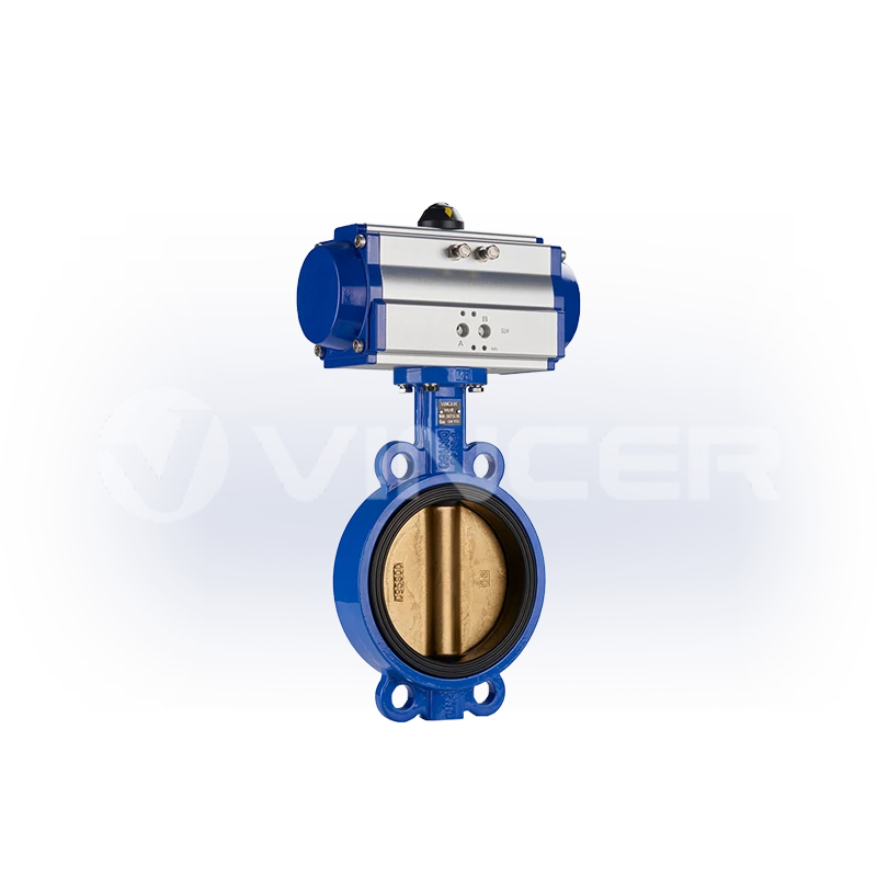
Пневматический дроссельный клапан представляет собой дроссельный клапан с привинченным пневматическим приводом — как правило, через тот же фланец, соответствующий стандарту ISO 5211. Сжатый воздух приводит в действие механизм «рейка и шестерня» внутри привода; привод преобразует давление воздуха в крутящий момент, действующий на шток клапана; шток поворачивает диск на те же 90°, что и ручной рычаг. Принцип работы самого клапана не меняется — меняется лишь источник привода.
Важными параметрами являются крутящий момент и подача воздуха. В качестве ориентировочного диапазона для задач с поворотом на четверть оборота: приводы с зубчатой рейкой двойного действия обычно обеспечивают крутящий момент примерно 8–4 700 Н·м, приводы с пружинным возвратом — около 5–2 800 Н·м, а более крупные приводы со скотч-йоком — до 10 000 Н·м при давлении в системе до 8 бар и температуре окружающей среды от примерно −20 °C до +80 °C, с временем хода менее секунды (серийные данные производителя). Если привод не может развить достаточного крутящего момента, чтобы прижать диск до полного закрытия, преодолев давление в трубопроводе, клапан будет “пропускать” — протекать вокруг диска — независимо от того, насколько качественно выполнено седло.
Single-Acting vs. Double-Acting: What Happens When the Air Goes Out
The first question engineers ask about pneumatic butterfly valves is what happens on air failure, and the answer is determined before the valve is ever ordered.
- Double-acting: air opens it, air closes it. If supply is lost, the valve stays where it is. Simple and cheap; no defined failure position.
- Single-acting (spring return): one direction is powered by air, the other by a spring. On air loss, the spring drives the valve to a defined fail-safe position — spring-to-close or spring-to-open.
Choosing between them is a process-safety decision, not a cost decision: chemical and water processes usually want spring-to-close (fail closed to contain the line), ventilation and dump services usually want spring-to-open. If your control system assumes “air loss = valve closes,” and the valve is double-acting, that assumption is fiction.
From On/Off to Modulation: Valve Positioners and Throttling
To make a pneumatic butterfly valve regulate rather than just open and close, it needs a valve positioner: a control loop that takes a 4–20 mA signal and moves the disc to a commanded angle, holding it there against process forces. This is where the butterfly’s flow characteristic enters the story, and it is not linear.
A butterfly valve has a roughly quick-opening characteristic: most of the flow change happens in the first part of the stroke. A small movement near the closed position produces a disproportionate flow swing, which is why a modulated butterfly valve is only comfortable working around the middle of its travel — engineering guidance puts the usable modulation band at roughly 30–60% open, with the valve often selected one nominal size smaller than the pipe so that the working point actually lands inside that band (Eng-Tips, valve engineering forum). What happens when you leave that band is covered later — but first, the other half of the automation story.
Specifying a pneumatic or electric butterfly valve?
Get the actuator matched to your duty — torque, fail-safe behavior and stroke time checked against your line size.
Ask for valve & actuator selectionMotorized Butterfly Valve Working Principle: Signal In, Torque Out
A motorized butterfly valve replaces the air muscle with an electric actuator: motor, gear train, and output drive mounted on the same ISO 5211 flange. The motor turns the gear train; the gear train multiplies torque and slows the output; the output turns the stem; the stem rotates the disc, to either of two positions (ON/OFF type) or to any commanded angle (modulating type with a 4–20 mA / 0–10 V signal).
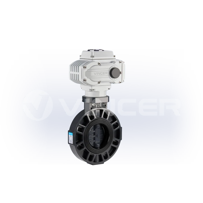
Torque and speed are the two numbers that decide whether the assembly does its job. As a reference band for quarter-turn electric actuators: output torques range from roughly 200 N·m for compact units (2.5–20 s stroke) up to about 4,000 N·m for large quarter-turn units (20–100 s stroke), with multi-turn versions beyond 10,000 N·m, in DC 12/24 V and AC 110/220/380 V variants (manufacturer series data). Electric actuation is the usual choice for precise modulating control, remote monitoring via PLC/SCADA, and sites without a reliable air supply.
How an Electric Actuator Turns the Disc — and Why Speed Matters
The power chain looks like this: signal → motor → gear reduction → output drive → stem → disc. The gear reduction is the part people misread. An electric actuator is slower than a pneumatic one because it trades speed for torque, and that slowness is often a feature, especially on large water lines.
Close a big butterfly valve too fast and you invite water hammer: the moving water column slams into the closing disc, and the pressure spike can damage valves, pipe supports, and pumps. A slow, controlled electric close over tens of seconds gives the water time to decelerate. When a pump station or water treatment spec calls for an electric butterfly valve, “how many seconds to close” is usually a deliberate engineering number, not an accident.
Electric vs. Pneumatic: Choosing the Driver for Your Duty
The two automation paths answer to different plant realities. The decision matrix that matters:
| Измерение | Electric | Пневматический |
|---|---|---|
| Speed | 20–100 s stroke — slow, controlled | Under 1 s — fast |
| Power source | Mains or DC supply | Compressed air — needs a dry, filtered supply |
| Hazardous areas | Explosion-proof electric actuators available (ATEX-rated) | No electrical spark in the actuator itself, but ATEX certification must still be verified per unit |
| Modulation | 4–20 mA precise positioning as standard | Needs a positioner for modulation |
| Failure behaviour | Stays put, or spring-return variant on power loss | Stays put (double-acting) or spring to a defined position (single-acting) |
| Maintenance | Motor and gear wear, occasional | Seal wear and air quality discipline |
Two cautions. First, “no spark” is not the same as “certified”: a pneumatic actuator’s inherent suitability for explosive atmospheres does not itself grant an ATEX rating. The complete assembly has to be certified. Second, ISO 5211 is the common language that lets an electric or pneumatic actuator from one manufacturer mount on a butterfly valve from another — so the actuator choice stays independent of the valve choice, and the working principle of each half can be matched to the duty separately.
That is also where buying the driver and the valve from the same factory pays off: the torque matching is done before the quote, not after installation. VINCER publishes its electric and pneumatic actuator range openly: quarter-turn electric units from 200 N·m (2.5–20 s stroke) up to 4,000 N·m (20–100 s), multi-turn versions to 10,000 N·m, plus explosion-proof and waterproof variants. Pneumatic rack-and-pinion AT/ATS/AW series run from 8–4,678 N·m double-acting and 5.7–2,792 N·m spring-return up to 10,000 N·m, with under-one-second stroke response and no electrical spark in the actuator itself. The same factory builds the valves those actuators bolt onto, including pneumatic actuated butterfly valves in wafer, flanged, sanitary, plastic, hard-seated and PTFE-lined versions, and electric butterfly valves from compact wafer and lugged types up to auto-reset power-off designs, in sizes from 2″ to 24″. One factory, one torque table, one set of pressure-test records, and the working principle of each half matched on paper before anything ships.
When the Working Principle Breaks: Throttling Limits and the 30–60% Rule
Everything above described the butterfly valve doing what it does well. This section is about where the principle stops holding, because that is the information that keeps plants out of trouble, and it is almost never written down in “working principle” articles.
The danger zone is below 30% open. At small opening angles, the flow area narrows to a crescent. Fluid velocity through it rises sharply, the disc sits at a steep angle, and local pressure can drop below vapour pressure. The result is cavitation: vapor bubbles forming and collapsing at the disc edge, eroding the seat and even the downstream pipe wall. Field experience puts the rule simply: a butterfly valve throttled below about 30% opening risks cavitation damage, and the damage typically shows up first on the seat (Eng-Tips).
The trap is sizing the valve the same size as the pipe. If you need to throttle, and the valve matches the line diameter, the required flow may only be achieved at 15–25% opening — exactly the cavitation-and-chatter zone. The standard fix in control practice: select the butterfly valve one nominal size smaller than the pipe for modulating duty, so the working point returns to a healthy mid-stroke position.
And the corollary for plant engineers: when the duty keeps a butterfly below 30% continuously, the answer is not a better butterfly — it is a different valve. The boundary matrix below is the horizontal version of everything above — scenario, valve, and the line not to cross:
| Scenario | Valve Choice | Граница |
|---|---|---|
| On/off isolation, large water or gas lines | Concentric soft-seated butterfly | Perfect — do not throttle it |
| Frequent flow adjustment (raw or process water) | Butterfly one size smaller than pipe, kept in 30–60% band — otherwise a control valve | Continuous <30% opening = switch signal |
| High-temperature, high-pressure tight shut-off (oil, gas, chemical) | Triple-offset metal-seated butterfly | Full closure mandatory; partial closure wears the metal seat |
| End-of-line isolation with one side maintainable | Lug butterfly with blind flange | Pressure rating drops in dead-end duty |
| Slurries, solids-laden media | Knife gate valve | Butterfly seats wear quickly on abrasives |
These boundaries are why the standards exist: butterfly valves for industrial duty are designed and tested to norms such as EN 593 (industrial butterfly valves) and API 609 (butterfly valve standard), and matching valve, seat, and actuator to the duty is precisely what a proper selection process, not a price sheet, is for.
What the Working Principle Means for the People Buying Valves
That last boundary, “when the duty keeps a butterfly below 30%, the answer is a different valve,” is a decision someone has to own. In the projects where these valves are specified, that ownership is exactly where the money leaks, because the people who choose the valve are usually not the people who suffer the failure.
Look at what actually happens in the field. Plant teams throttling raw or process water with a butterfly valve watch the seat die within a short operating window and the valve lose both control and isolation duty, the classic “seat damage in flow-adjustment service” story from the engineering forums. The root causes are always the same three, and all three are decisions made before the valve is ever bolted in. The valve was sized to match the pipe instead of the duty. The working opening was left in the 15–30% zone instead of the 30–60% band. And the seat material was chosen by price rather than by media temperature. None of these show up on a drawing. They show up as downtime, and downtime is the most expensive line item on any valve’s lifetime bill.
For the people buying these valves, the translation is direct. In project procurement, put three clauses in the specification: the valve-to-pipe size ratio for any modulating service, the required working opening band, and the seat material temperature ceiling for the actual media — and the seat-damage failures largely stop being your problem. For equipment OEMs, document the failure behaviour (fail-open or fail-closed on air/power loss) in the selection documents, because a control philosophy that assumes the wrong failure position is a safety incident waiting for a power cut. And when comparing suppliers, price the selection as much as the valve: an assembly that cannot close fully because the actuator is under-torqued is a leak, a rework, and a claim — not a discount.
Three clauses that belong in the specification
Now for where the money actually sits in this product family — because it matters for every buyer, and especially for distributors and equipment builders deciding what to stock. A bare butterfly valve is close to a commodity: its price is on every directory, and its margin gets squeezed toward zero. The actuated assembly is a different product. The moment you add an actuator, the value moves into things a catalogue price cannot express: torque matching against the valve’s actual seat load, the ISO 5211 interface decision, the fail-safe logic, the control integration. That is engineering work, and engineering work cannot be commoditized. The market data in the decision-point section said the same thing from the demand side — automation is where the growth is — and the profit follows the same direction. If you are building a product line or a stock list around butterfly valves, the defensible position is the actuated assembly: valve plus actuator, matched and tested as one unit. The bare valve is the entry ticket; the actuator is where the margin lives.
That is also why the supplier question is really a capability question. The working principle itself is public knowledge — every manufacturer’s website explains the 90° turn. What separates suppliers is what happens before the quote: whether the valve, seat, and actuator are matched to media, temperature, pressure, connection standard, control method, material, and industry characteristics — the full selection screen, not just the price column. On the delivery side, the published figures matter. Stock items leave in about five working days, custom builds in about twenty, per the manufacturer’s own published lead times (pneumatic valve page FAQ). And when a valve “won’t close,” “won’t install,” or “leaks,” the after-sale response — free spare parts, remote technical guidance, engineers who analyse before replacing — is the difference between a week of downtime and a morning.
When the working principle has to be matched to a real duty — media, temperature, pressure, connection standard, control method, body material and industry characteristics — that matching is selection engineering, and it is where the supplier’s actual capability shows. Send your duty to VINCER’s selection engineers and get a proposal within 48 hours, starting from their butterfly valve range.
Get your butterfly valve selection checked against the 30–60% rule
Send your line size, media, temperature and pressure — the engineering team replies with a selection proposal.
Request a selection proposalReferences
- Wikipedia. “Butterfly valve” — quarter-turn definition, disc-in-flow, wafer/lug dead-end pressure derating. https://en.wikipedia.org/wiki/Butterfly_valve
- Tameson. “What is a Butterfly Valve?” — seat material temperature limits, ISO 5211/NAMUR mounting, selection criteria. https://tameson.com/pages/butterfly-valve
- Eng-Tips (Valve Engineering forum). “Butterfly Valves used for flow adjustment in raw water service experiencing valve seat damage” — 30% cavitation line, 30–60% throttling band, oversized-valve rule. https://www.eng-tips.com/threads/butterfly-valves-used-for-flow-adjustment-in-raw-water-service-experiencing-valve-seat-damage.459593/
- MarketsandMarkets. “Actuators Market — Global Forecast to 2030” — USD 71.22B (2025) → USD 100.41B (2030), CAGR 7.1%, all actuator types (electric/hydraulic/pneumatic). https://www.marketsandmarkets.com/Market-Reports/global-actuators-market-59465451.html
- VINCER Valve. Butterfly valve series — wafer/lug/double-flanged, 2″–24″, sealing options. https://www.vincervalve.com/vincer-butterfly-valve-series/
- VINCER Valve. Contact for a quote. https://www.vincervalve.com/contact-for-a-quote/
- VINCER Valve. Homepage. https://www.vincervalve.com/
- VINCER Valve. Electric and pneumatic actuator range — VQ/VM quarter-turn, multi-turn, explosion-proof, waterproof electric; AT/ATS/AW pneumatic; torque 200 N·m–10,000 N·m. https://www.vincervalve.com/vincer-automatic-valve-actutors/
- VINCER Valve. Pneumatic actuated valves — pneumatic butterfly valve family (wafer, flanged, sanitary, plastic, hard-seated, PTFE-lined); response <1 s; hazardous-environment suitability. https://www.vincervalve.com/pneumatic-actuated-valve/